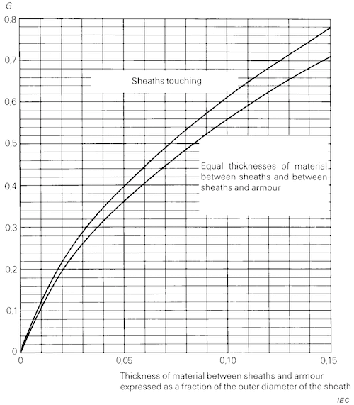
The geometric factor for three-core cables with separate sheaths is the digital calculation of the quantity G given graphically in IEC 60287-2-1, Figure 6, used to calculate the thermal resistance of filler material and armour bedding as part of $T_2$ for cables with separate sheaths. In case of CIGRE TB 880 Guidance Point 45, the first two equations are being used.
For unarmoured three-core cables with extruded insulation and individual copper tape screens on each core, the thermal resistance of the fillers and binder is in $T_2$ and not in $T_3$ as in IEC 60287. In this case, the third and fourth equations are being used.
The equation for three-core cables with jacket around each core is based on the Jicable paper 'Thermal analysis of three-core SL-type cables with jacket around each core using the IEC standard' by L.D. Ramirez et al., dated 2019.
| $2\pi \left(0.00022619+2.11429X_{G2}-20.4762{X_{G2}}^2\right)$ | sheaths touching or CIGRE TB 880 Guidance Point 45, $0 < X_{G2} <= 0.03$ |
| $2\pi \left(0.0142108+1.17533X_{G2}-4.49737{X_{G2}}^2+10.6352{X_{G2}}^3\right)$ | sheaths touching or CIGRE TB 880 Guidance Point 45, $0.03 < X_{G2} <= 0.15$ |
| $2\pi \left(0.00020238+2.03214X_{G2}-21.6667{X_{G2}}^2\right)$ | equal thickness between sheaths and between sheaths and armour, $0 < X_{G2} <= 0.03$ |
| $2\pi \left(0.0126529+1.101X_{G2}-4.56104{X_{G2}}^2+11.5093{X_{G2}}^3\right)$ | equal thickness between sheaths and between sheaths and armour, $0.03 < X_{G2} <= 0.15$ |
| $G_{FEA}+G_{corr}$ | three-core cables, jacket around each core, $0 < X_{G2} <= 0.15$ |
IEC standard 60287-2-1 Ed. 2.0 (2015) Figure 5