SSL encrypted & Cloudflare protected


Equations can be included in the calculation reports and the cable datasheets. Where multiple cases with different formulas exist for a certain parameter, the software always takes the exact formula which was used for the specific system and cable.
We don't use pictures, we actually write the correct and complete formula.
The simulation results are being displayed online and you are free to download them as high-end PDF. The results include all input parameters necessary to set up the study and all the main output data.
Missing data on the report? All parameters and results used by the database can be printed! Let us know!
The content of the cable datasheets can be defined in a flexible way. One can define which parameters to include or not.
For this, the software calculates many additional parameters such as mass of all cable layers, minimal bending radius, gross heat of combustion value, heat energy content, embodied energy, embodied carbon, cost of metals in the cable
You can create laying arrangements with up to 20 systems made out of different cable systems, all having different frequencies, loading, load factors, in pipes, directly buried, etc.
Add heat sources, duct banks, backfills, consider drying-out, fill ducts with bentonite, etc.
Cableizer is the only software in the market able to calculate the current rating for up to 6 different, unequally loaded cable systems in ventilated tunnels. The method is our own development and was presented at Jicable'19 in Paris.See
Other methods you can choose from are the Heinhold and IEC 60287-2-3 method.
Download the full paper at researchgate.com
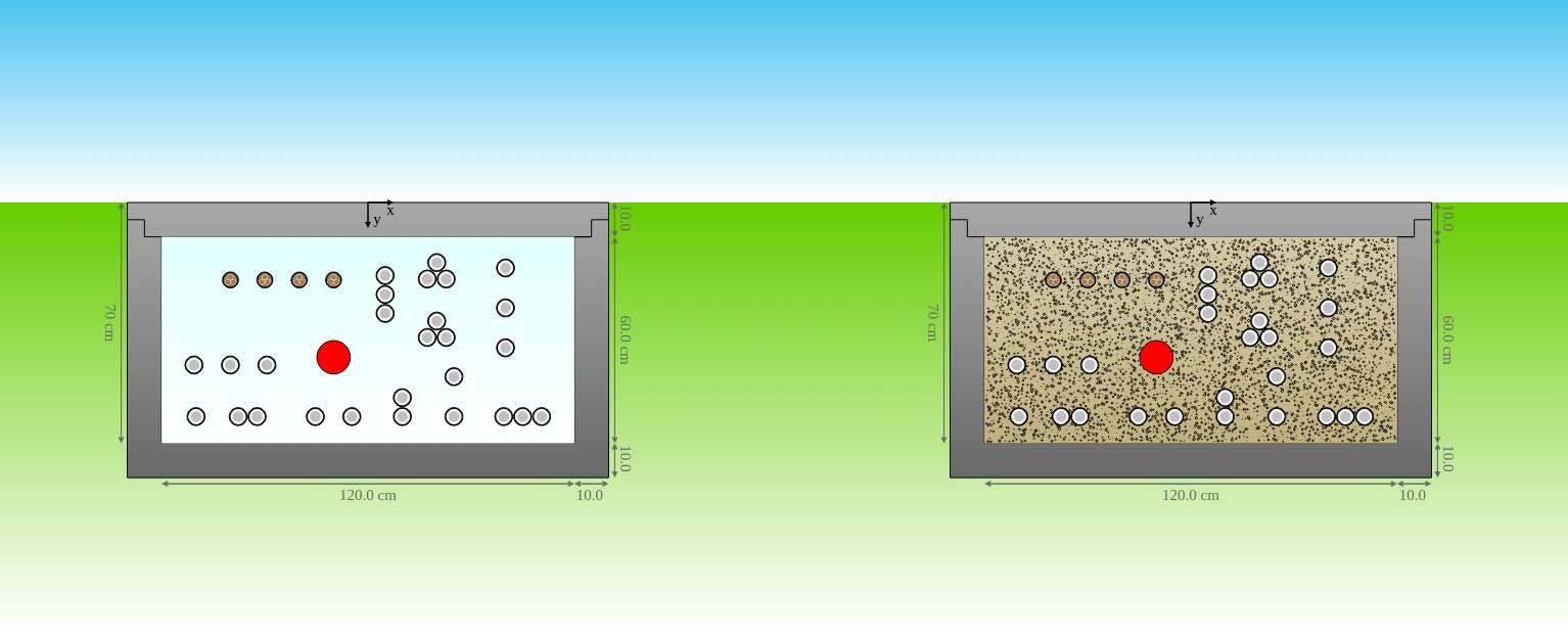
You can calculate the cable current rating for multiple different cable systems or heat sources in empty or filled troughs.
Choose from five methods: IEC 60287, IEE Wiring Regulation (BS 7671), Slaninka I with all equal resistivities, Slaninka II with different resistivities, or Anders extending Slaninka II for empty (air-filled) troughs.
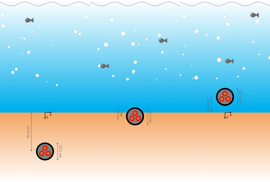
You can calculate the cable current rating for a subsea cable including parallel heat sources. The subsea cable can be fully buried, partially buried and completely in water. calculation method: IEC, Carslaw & Jaeger, Morud & Simonsen, Ovuworie, OTC 23033
The heat increase at specific depth can be calculated to consider the 2K criterion.
You can calculate the cable current rating for cables installed in J-tubes with four different methods:
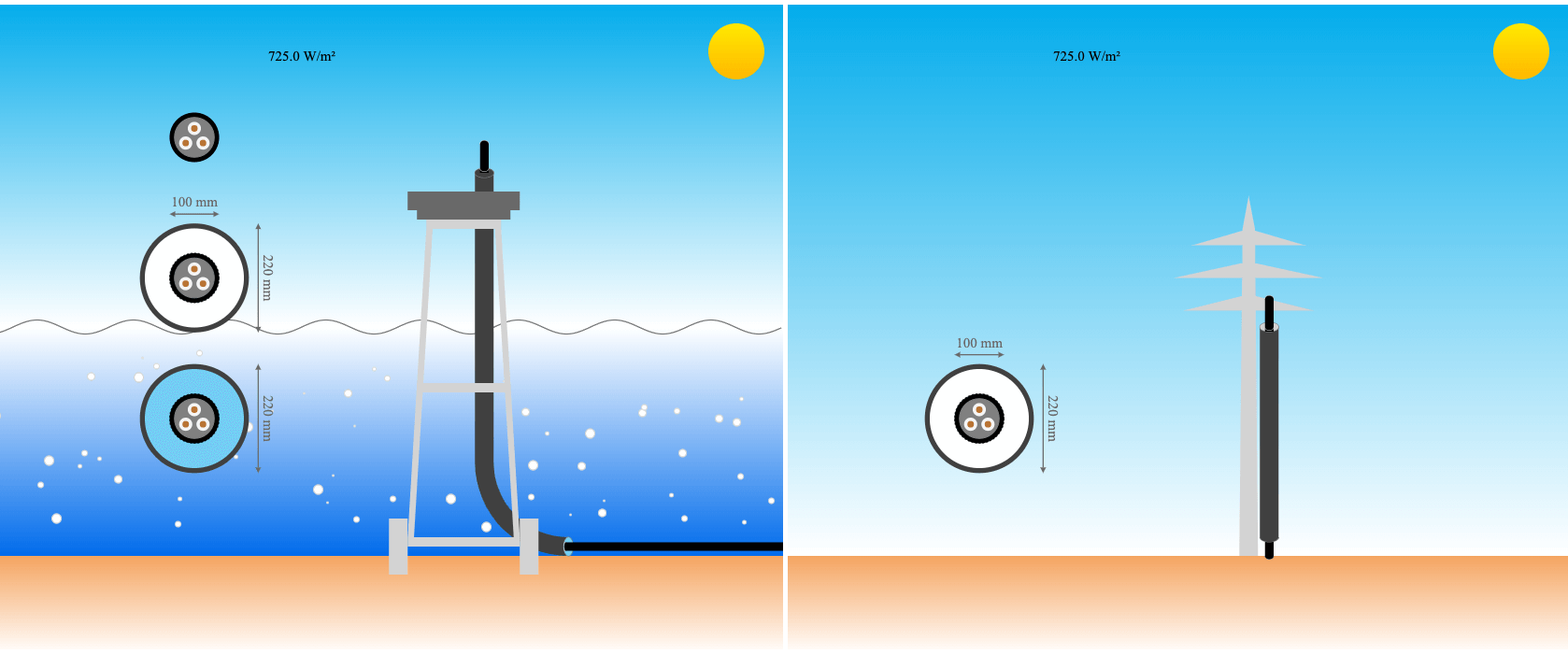
All options offered by IEC can be used, plus cables in pipes and grouped cables with solar radiation. You can set the spacing to smaller values than given in the IEC and use groups of two touching cables currently not covered by IEC standard.
You can setup an electrical system with multiple sections with different cables and lengths and calculate induced voltages and electrical parameters based on nominal load and during short-circuit conditions.
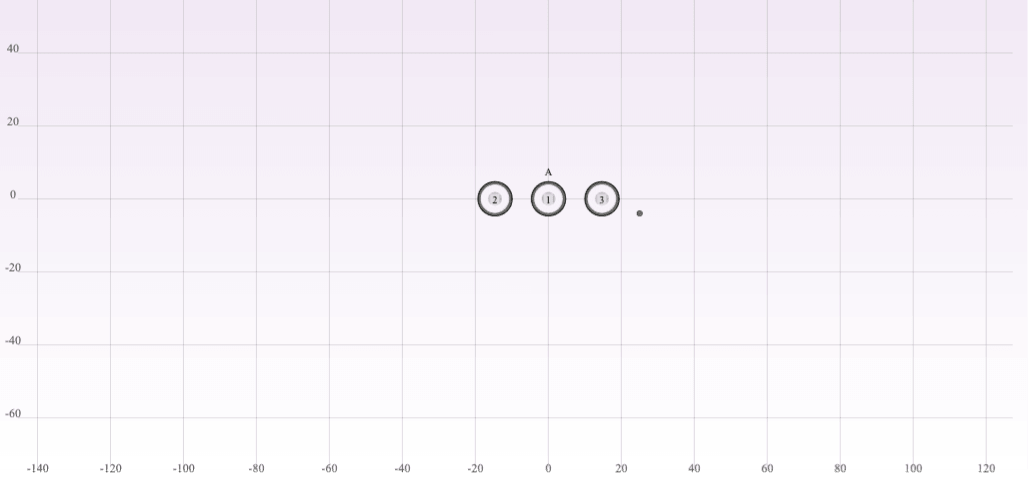
You can setup a cable system and calculate the mechanical forces.
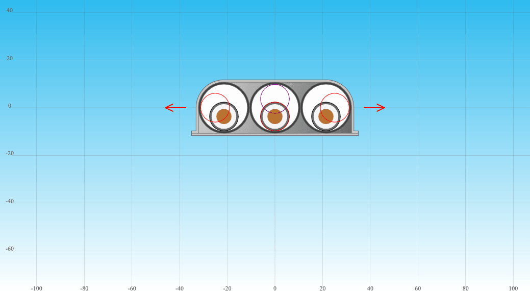
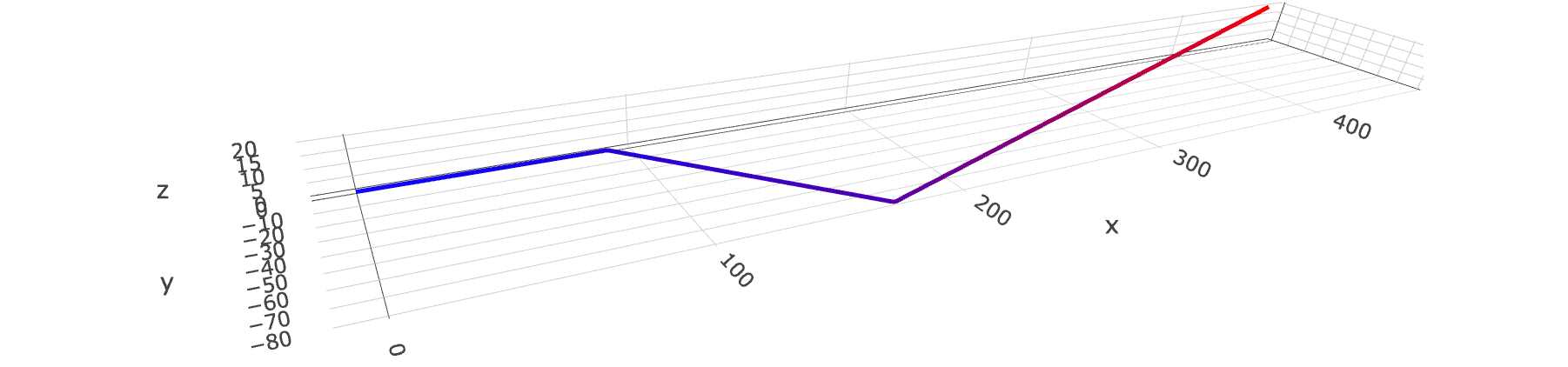
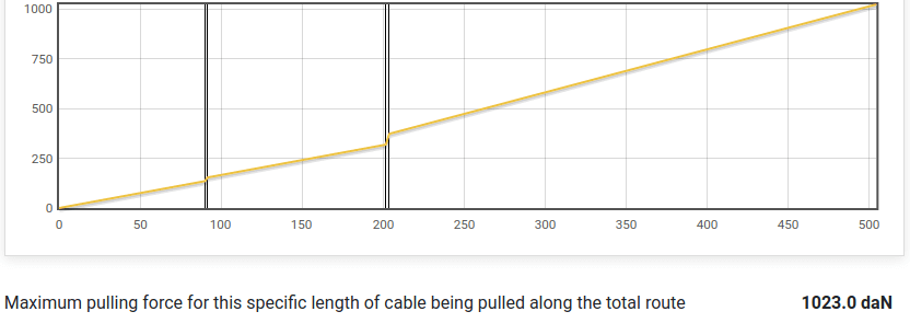
Model the cable route with sections, slopes, bends and cable pushers with 2D/3D preview and calculate the pulling tension.
Cableizer can calculate the pulling forces of cables being pulled over a route longer than the cables.
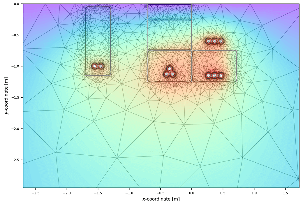
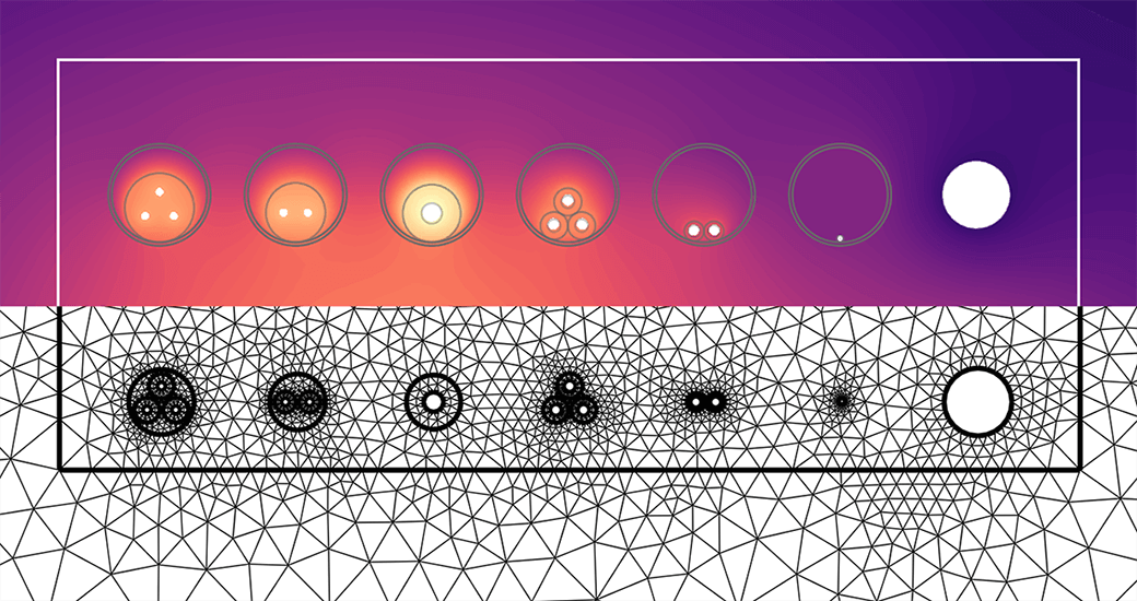
With the newly introduced method, it is possible to calculate the external thermal resistance of all buried objects using finite element calculation.
The extensive python FEM module PyGimli is used for all our applications using the finite element method, including the calculation of the temperature distribution. Thanks to the contributors of PyGimli.
This analytic method allows to model cables and cables in ducts to be places within an air-filled buried pipe. Such an installation is found in horizontal and directional drillings and small tunnels. The calculation is using the principles of buried cables including air-filled ducts and cables in air-filled troughs where the temperature of the air-space is calculated iteratively considering the losses of all containing systems.
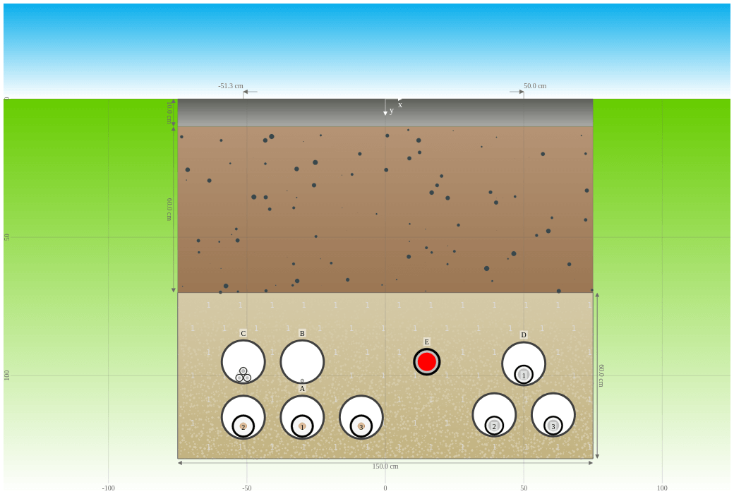
With the multi-layer backfill method, it is possible to simulate the filling of a rectangular trench where the cables are buried with two superimposed horizontal layers of different materials.
The multilayer backfill can be used in two ways, either an analytic method using parameters derived from extensive FEM calculations or using our finite element method to calculate the external thermal resistance. The latter case allows to add additional backfill areas.
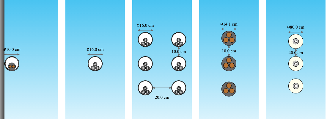
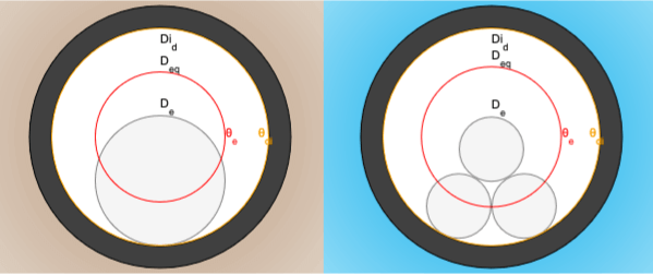
You can place up to 12 cables inside the same duct for systems being buried or in air.
Their position inside the duct is automatically set depending on inner duct diameter.
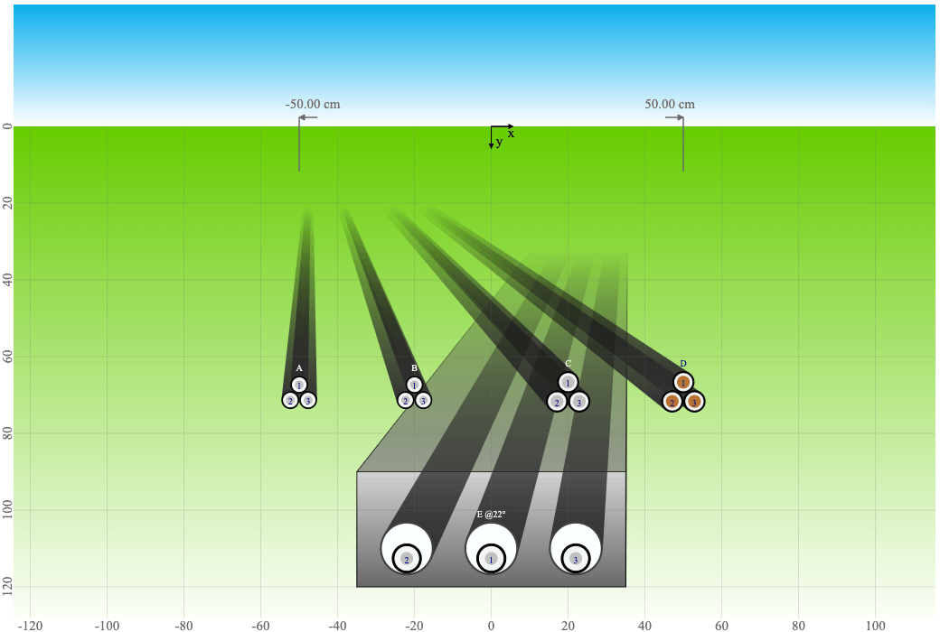
You can calculate the crossing at any angle of one or multiple cable systems with one or multiple other cable systems or heat sources.
Cableizer was the first software in the market able to calculate multiple crossings using an intelligent iterative procedure. The method is our own development and was presented at Jicable'19 in Paris.
Download the full paper at researchgate.com
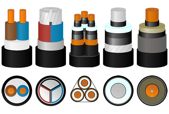
Cableizer is suitable to model power cables of all voltage range, be it 230 V or 500 kV; AC or DC cables; one-, two- or three-core cables; with all kind of materials for conductor, insulation, screen/sheath, armour and jacket.
You can define and store as many individual cables and project as you like. We also offer you a library with more than 100 sample cables.
You can create heat sources with fluids and multiple layers, just like a district heating pipe.

You can create a fiber optic cable (FOC) to be used as a temperature sensor.
Pressurized air cable (PAC, Hivoduct) or gas insulated line (GIL, see entso-e). PAC/GIL can have hollow or solid conductors of different materials, a gas compartment with pressurized dry air, nitrogen, SF6, CO2, or gas mixtures and a protective cover.


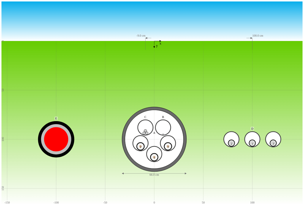
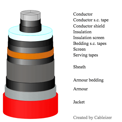
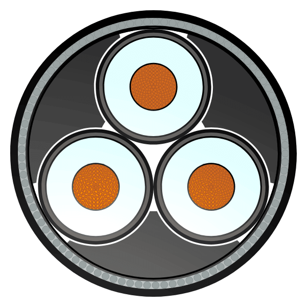
Cableizer uses sophisticated code to visualize the cable in a 2D and 3D model and to update instantly after changes in the editor.
The dimensions of both previews are to scale for each layer relative to the others.

Calculate the temperature distribution in the soil and show the increase in temperature due to power cables or heat sources/sinks. It is available for modules buried, subsea, tunnel and trough.
You may choose superposition principle or finite element method.
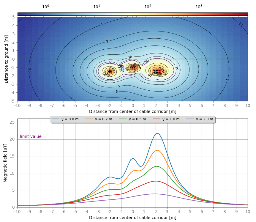
You can calculate the magnetic field of multi-frequency systems, set the load flow or a phase-shift for each system. The output is in brilliant 2D isolines and in 1D lines above ground.
Magnetic field calculation is possible for all modules: in air, buried, subsea, tunnel, trough, and riser. Several settings can be made such as plot width, isolines and colormap.
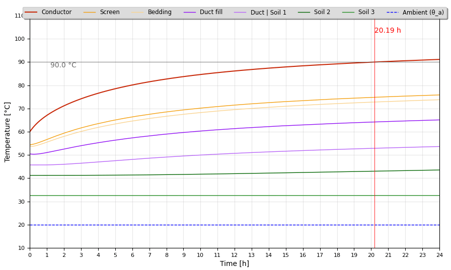
Run a calculation of emergency rating of cable systems or any transient step response of the temperatures of a cable system. The method uses state-space representation with multi-layer cable, duct and environment (multi-layer soil, air, trough, tunnel) modeled as a lumped RC-ladder network.
The voltage gradient induced in a cable shield may be considered as a special case in which the parallel conductor is a shield at a spacing from the conductor that it embraces equal to the mean radius of the shield. When no other current-carrying conductor is in the vicinity.
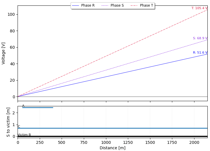
This tool calculates the induced current in a chosen insulated earth continuity conductor (victim) due to magnetic coupling from surrounding loaded cables. Conductors are modeled as filament currents and the magnetic field coupling is evaluated using Biot–Savart-based mutual inductance per unit length with earth-return approximation. By specifying start/end positions, the tool considers full or partial parallel exposure and plots both the induced current profile and the active parallel systems along the route.

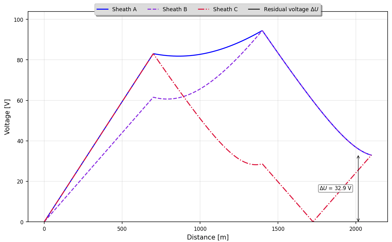
This tool calculates the induced longitudinal voltage on a chosen de‑energized (victim) cable system due to magnetic coupling from surrounding loaded cables. Conductors are modeled as filament currents and the magnetic field coupling is evaluated using Biot–Savart-based mutual inductance per unit length with earth-return approximation. By specifying start/end positions, the tool considers full or partial parallel exposure and plots both the induced voltage profile and the active parallel systems along the route.
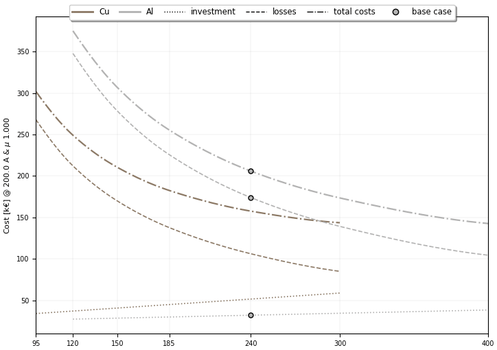
The cable-sizing procedure commonly used in practice typically selects the minimum permissible conductor cross-sectional area, thereby minimizing the cable's initial purchase cost. However, it does not account for the cost of electrical losses incurred over the cable’s service life. Instead of minimizing the upfront cost alone, the total lifetime cost—i.e., the sum of the initial cost and the present value of loss-related costs over the expected operating life—should be minimized. When a conductor size larger than the thermal minimum is selected, the reduction in Joule-loss costs can outweigh the higher purchase cost, resulting in a lower overall cost.
The formulas used in this tool are based on the international standard IEC 60287-3-2.
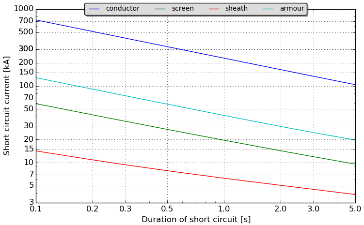
The short-circuit rating of any current carrying component of a cable - conductor, screen, sheath and armour - is calculated according to the standard IEC 949, taking into account non-adiabatic heating effects.
Initial temperature is taken from the ampacity calculation results directly to ensure worst-case scenario.
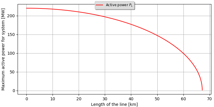
The maximum transmitted power in an underground radial link is dependent on the frequency, length and voltage across the insulation. However a large conductor can transfer higher loads than a smaller conductor can. Therefore the charging current becomes of less importance when the conductor area becomes larger, if the generated power is unchanged. Assuming purely resistive loads and no compensation, the power transfer of a long cable system can be found.
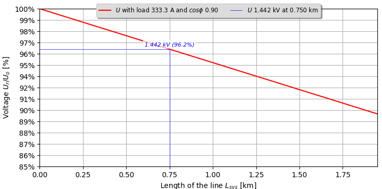
For the calculation of voltage drop along a cable, one may enter a specific load (kW), the power factor (cosφ), and the length of the cable line. The power factor is the ratio of active power to apparent power and when the waveforms are purely sinusoidal the phase angle φ between the current and voltage.
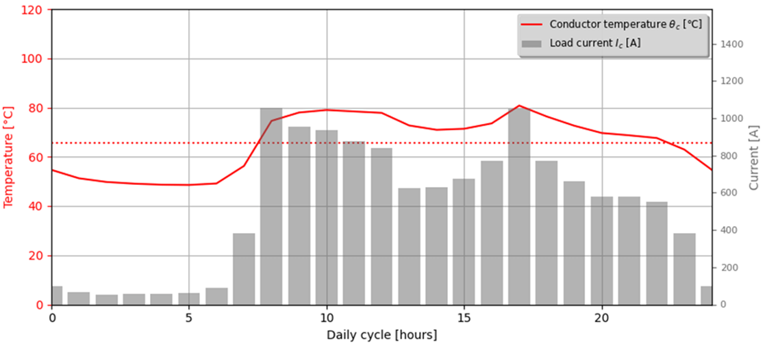
We provide a cyclic rating method acc. IEC 60853 considering the corrections made by CIGRE WG B1.72.
Using the CIGRE methodology allows to includes a plot of temperature variation over the load cycle period period. We are using a combination of methods by IEC/CIGRE and Dorison which allows calculation of mutual heating between all systems even for a mix of all load methods, including steady-state, cyclic with load/loss factor, and cyclic rating based on IEC/CIGRE.
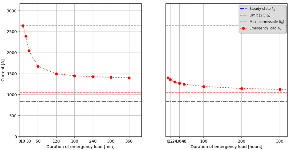
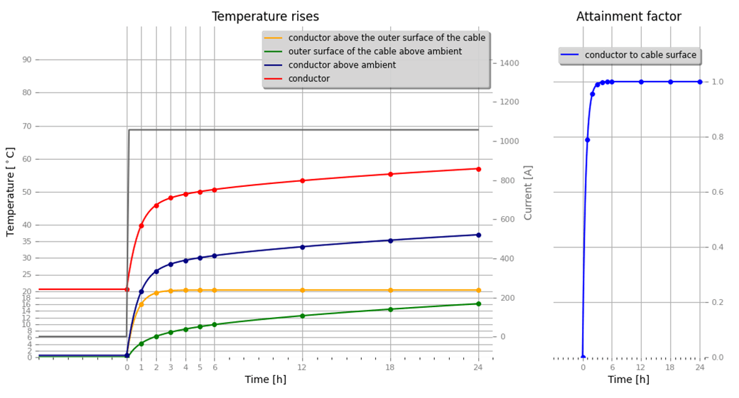
We provide an impressive emergency rating calculation acc. IEC 60853 and optionally considering CIGRE WG B1.72.
The output in the report includes all parameters for a specific user-defined emergency period. In addition, a plot is provided which shows the emergency rating current for a wide time range.
You can calculate transient step current calculations for one or several steps.
Duration of one step can be 10 minutes (lower limit of IEC 60853), hours or even days. The preload is calculated using steady-state method according to IEC 60287 with the temperatures at $t = 0$ being calculated using the same transient method over 10 days prior.
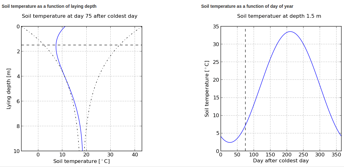
The soil temperature calculator helps you to estimate the ambient soil temperature at a particular lying depth and day of year. In climates with distinct seasons one observes temperature changes in the uppermost soil meters. The upper soil layers are heated in the summer, while the deeper layers are still cold.
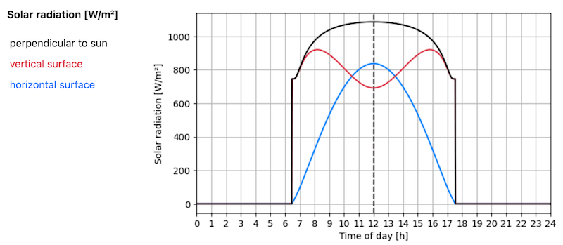
The solar radiation calculator is a tool that estimates the intensity of solar radiation for a given day and a given place depending on its location and altitude.
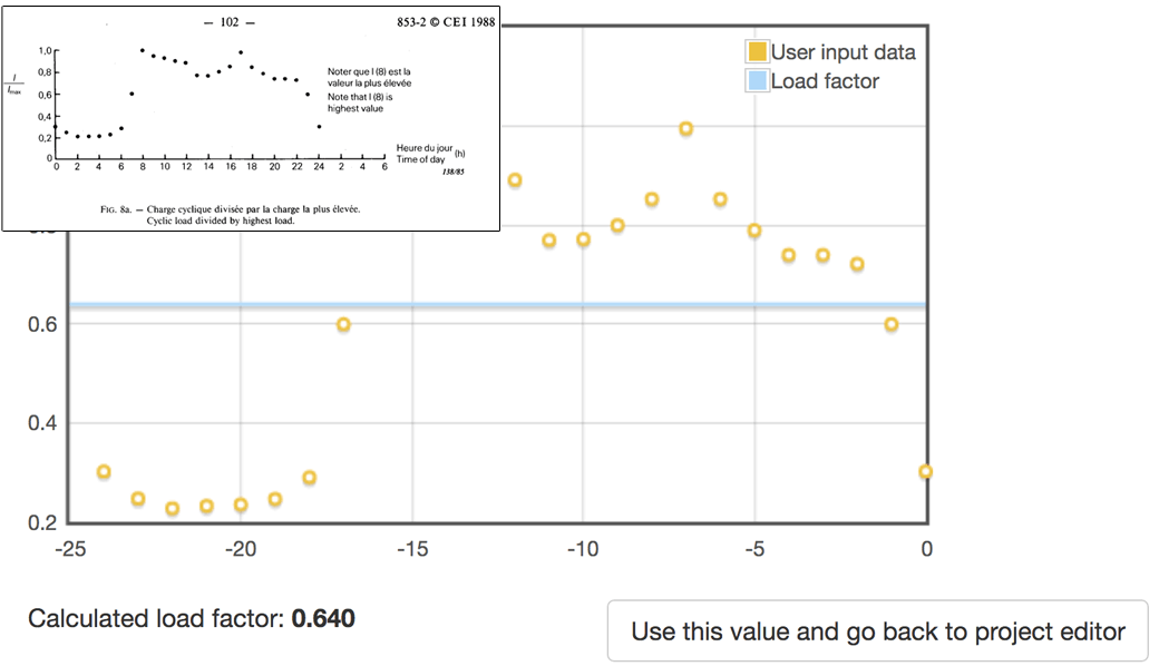
The load factor calculator is a tool that calculates the squared ratio between the average power and the maximum demand in a period of time.
$$LF=\frac{D_{average}}{D_{max}}=\frac{I}{D_{max}} \frac{ \sum \limits_{t=0}^T D(t)dt}{T}$$
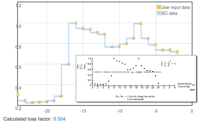
The loss factor calculator is a tool that calculates the ratio between the average power losses and the losses during peak load in a period of the time. In other words, the loss factor is simply the load factor of the losses.
$$\mu=\frac{L_{average}}{L_{max}}=\frac{I}{L_{max}} \frac{\int\limits_{t=0}^T L(t)dt}{T}$$
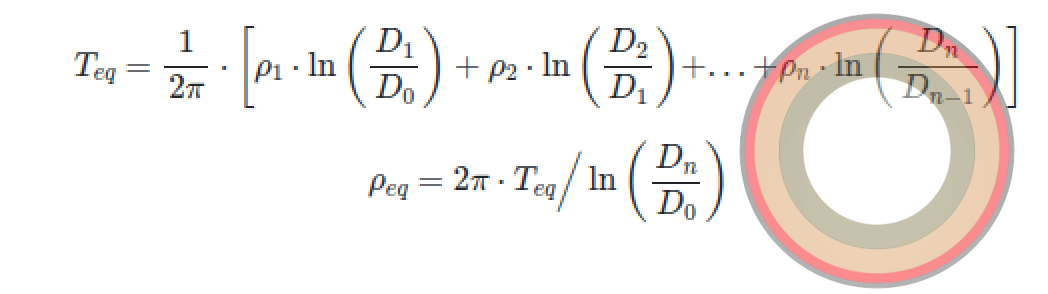
The equivalent resistivity calculator can be used to determine the thermal resistivity of a cable insulation or jacket material consisting of multiple layers with different thermal resistivities.
cross-bonding f-factor" data-bs-content="Where a cross-bonded installation contains sections whose unbalance is not negligible, a residual voltage is produced which results in a circulating current loss in that section which must be taken into account. The circulating current loss factor for the cable configuration concerned is to be multiplied by a certain factor f.
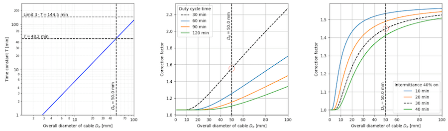
The cable calculator for ships determines the short-cycle duty rating and intermittent service rating for cables used in fixed electrical systems on board ships, operating at voltages up to 15 kV, in accordance with the international standard IEC 60092-352.
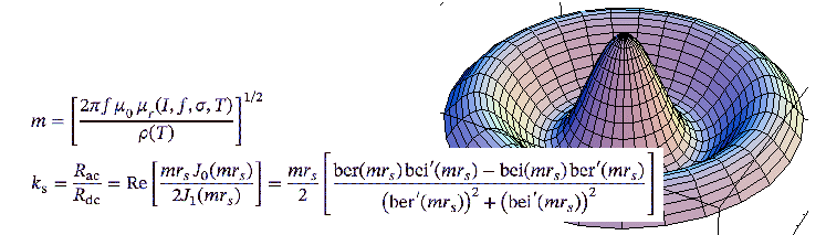
conductor resistance" data-bs-content="Skin effect in solid round circular conductors and proximity effects between solid round circular conductors were deeply investigated, specially by A.H.M. Arnold, and formulae were worked out for $y_s$ and $y_p$, through tedious calculations to approximate the Bessel's functions involved in the solution of Maxwell's equations.
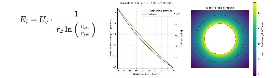
The value of the voltage gradient at point x within the insulation can be calculated using a logarithmic relationship. The electrical field strength is highest above the conductor shield (inner semi-conducting layer), below the insulation and lowest below the insulation screen (outer semi-conducting layer), above the insulation.
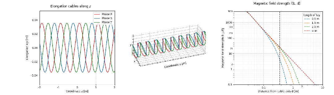
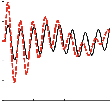
Twisting cables reduces the magnetic field because the current direction alternates along the cable length, causing the individual magnetic fields to partially cancel each other out. By twisting, the opposing fields are more evenly distributed and destructively interfere, significantly reducing the net external magnetic field.
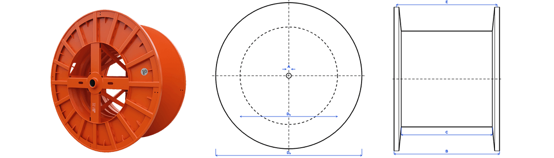
The Cable Drum Calculator is a tool that calculates the capacity of a specific cable on a cable drum.
When any element of the electrical network is energized, a transient process usually occurs. Inrush current may also occur when the cable line is switched on.
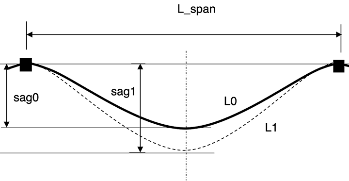
Sag is the vertical drop of a suspended cable from the support-to-support line to the lowest point of the cable.
Thermal resistance of the medium in a duct calculated with IEC 60287-2-1 is limited to diameters of cables 25 to 100 mm and of ducts 75 to 125 mm. An analytic method is used to calculate the thermal resistance outside this range.
Do you have a specific analysis or application in mind? Let us know!