We have been doing a general revision of the cable crossing module in Cableizer, with improvements of the preview as well as the reporting. Setting up a cable crossing simulation and evaluating its results is now significantly clarified.
Posted 2021-03-12
Categories:
New feature
, User guides
The preview of the cable crossing module has now been improved with 'tails' that clearly show which cables or heat sources are crossing each other. Please note that the preview is not an exact 3D representation, but more of an illustration. The following animation shows the crossing of a trefoil cable system at a depth of 70 cm with a flat spaced cable system located underneath at a depth of 110 cm. The crossing angle varies between +90° and -90° for illustrative purpose.
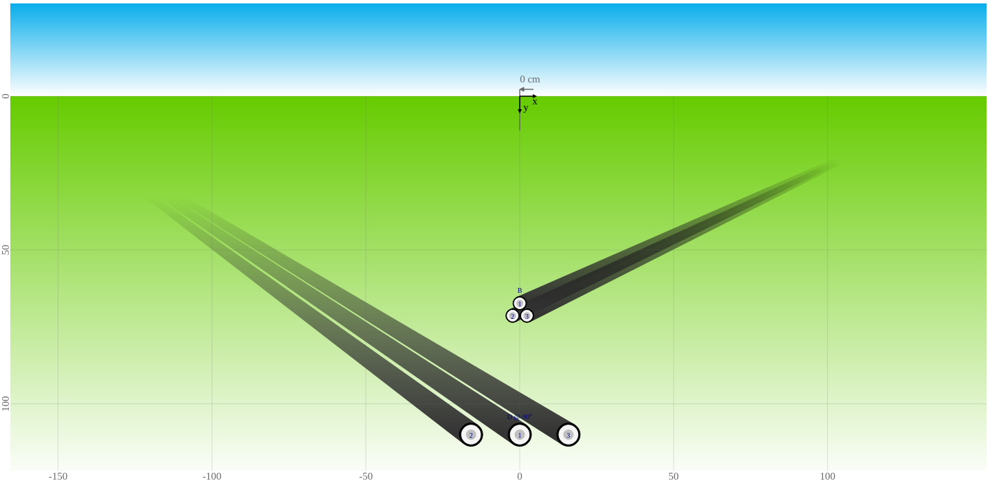
In order to present the improvements on the reporting, we have done a simple simulation of the above cable arrangement, with the crossing angle fixed at +90° (as shown above beside the animation). The trefoil cable system had a temperature limit of 65 °C, while the flat spaced cable system had a fixed current of 520 A.
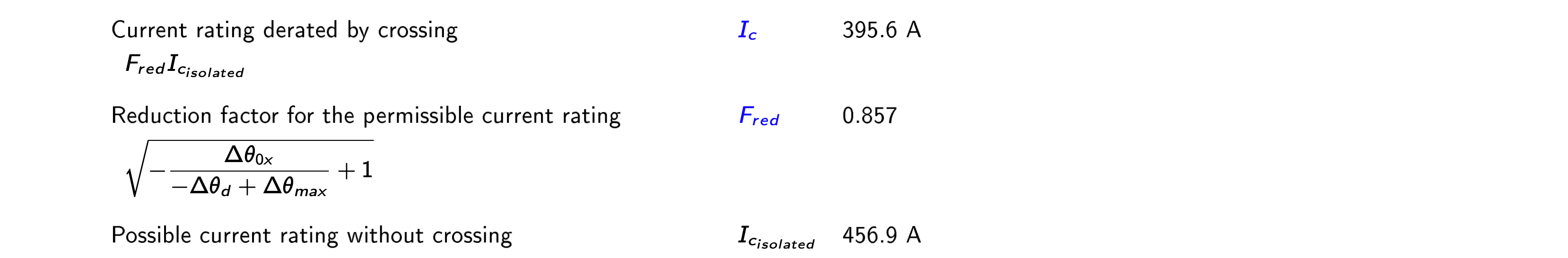
For the trefoil system, which is a temperature limited system, the report does now clearly list the possible current rating without crossing $I_{c_{isolated}}$ the reduction factor applied on the permissible current rating $F_{red}$ and the current rating derated by the crossing $I_c$.
The following table shows the results from three different simulations:
The first simulation is the crossing simulation with a fixed temperature limit of 65 °C. It gives us the temperatures and losses at the crossing. The temperatures at the crossing are the highest along the cable route and are a limiting factor for your cable design.
The second simulation is an isolated simulation of only the trefoil system, with the same current as the first simulation. This gives us the temperatures and losses away from the cable crossing. These losses are the most relevant considering that the cable route is generally much longer than the small part of it that is heated up by the crossing systems.
The third simulation is an isolated simulation of only the trefoil system, with the same temperature limit as the first simulation. It shows the possible ampacity if the crossing system should be turned-off or decommissioned.
| Current $I_c$ [A] | Temperature $\theta_c$ [°C] | Losses $W_{sys}$ [W/m] | |
|---|---|---|---|
| at the crossing (temperature limited) | 395.6 | 65.0 | 45.7 |
| away from the crossing (current defined) | 395.6 | 50.9 | 43.7 |
| without crossing (temperature limited) | 456.9 | 65.0 | 60.8 |
For the flat spaced system, which is a current defined system, the report does now clearly list the temperatures at the crossing as well as away from the crossing. The temperature rise by crossing heat sources $\Delta \theta_{0x}$ is also clearly indicated. The following figure shows the example of the conductor temperature $\theta_c$.

The following table shows the results from three different simulations:
The first simulation is the crossing simulation with a fixed current of 520 A. It gives us the temperatures and losses at the crossing. The temperatures at the crossing are the highest along the cable route and are a limiting factor for your cable design.
The second simulation is an isolated simulation of only the flat spaced system, with the same current as the first simulation. This gives us the temperatures and losses away from the cable crossing. These losses are the most relevant considering that the cable route is generally much longer than the small part of it that is heated up by the crossing systems.
The third simulation is an isolated simulation of only the flat spced system, with the temperature limit set to the value of the first simulation. It shows the possible ampacity if the crossing system should be turned-off or decommissioned.
| Current $I_c$ [A] | Temperature $\theta_c$ [°C] | Losses $W_{sys}$ [W/m] | |
|---|---|---|---|
| at the crossing (current defined) | 520.0 | 73.7 | 67.5 |
| away from the crossing (current defined) | 520.0 | 64.9 | 66.5 |
| without crossing (temperature limited) | 562.3 | 73.7 | 78.0 |
Please note that all losses of cable crossing simulations are now reported at the crossing. This is clearly stated in the report in order to avoid misunderstandings:
"The losses in this report are the maximum losses at the crossing."