Considerations about how to define the load of a system and how this choice influences the simulation results in Cableizer.
Posted 2021-06-15
Categories:
New feature
, Tips and tricks
, User guides
A heat source can be defined either by the surface temperature $\theta_{hs}$ in °C or the heat dissipation $W_{hs}$ in W/m. A positive value of heat dissipation represents a heat source, while a negative value represents a heat sink.
The load of a cable or GIL system can be define in three different ways:
Theoretically, it should not matter how you define your system load. A system with a certain conductor temperature $\theta_c$, conductor current $I_c$ and outer surface temperature $\theta_o$ should result in the same simulation result independent of choice of load method. However, in practice and under certain conditions, the above methods are of different robustness.
When simulating a lot of systems, systems that are coupled in parallel, and using advanced soil models (such as backfills or drying-out of the soil), the robustness of the load methods may vary. Some methods may result in oscillations and the solver might not converge.
The most robust method is to define the load of your systems with their conductor current. Whenever you face problems with solver convergence, change your critical systems to this method.
The least robust and newest method is to define the load of your systems with their outer temperature. This method is currently only recommended for relatively simple arrangements.
When the load of a system is defined by the conductor current or the outer temperature, a maximum allowable conductor temperature can still be provided (optional). Cableizer will then issue a warning in the simulation report if this value is exceeded.
NEW! When the load of a system is defined by its temperature (either $\theta_{cmax}$ or $\theta_{omax}$), the situation can occur that the system will exceed this temperature already unloaded, i.e. with $I_c$ = 0 A. Previously, the solver could not find a suitable load current and the simulation did not converge. With out latest solver update on 2021-06-09, this behaviour has been changed.
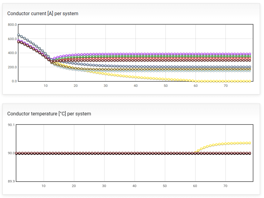
The following example of convergence curves show that no valid current could be found for the yellow system in order to keep it within the 90 °C conductor temperature limit. The updated Cableizer solver now fixes the conductor current of the yellow system to 0 A and calculates the overtemperature of this system (which is negligible in this specific case).
To ensure that this overtemperature is noticed, both the conductor current (0.0 A) and the conductor temperature are displayed in bold red font in the system overview of the report. In addition, every system that has an overtemperature already unloaded displays the following warning:
Warning! The conductor temperature exceeds the maximum allowable temperature of x.x °C for normal operation.