Results from cable crossing simulations can sometimes be confusing at a first glance. Based on a real example, we investigate the influence of the crossing angle on the cable rating.
Posted 2021-03-29
Categories:
User guides
When doing a crossing calculation we typically have the situation that new systems are crossing an existing heat source, like a heat pipe or existing cable system. The losses of these existing systems are generally known. What will happen is that their temperature will increase due to the additional losses from the new systems crossing them.
To show you the effect of this temperature increase, we present you here an example. We want to calculate the systems A, B, and C crossing an existing system D. This system D has a predefined rating which must be respected. Therefore, we set a fixed current for system D in our simulations.
There will be three steps:
| Preview of the two arrangements | Preview at the crossing |
|---|---|
 |
 |
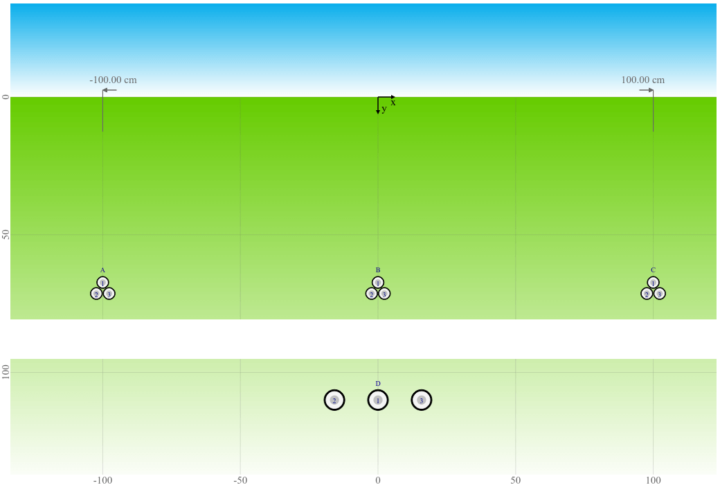
First we calculate the systems going straight and the systems crossing separately at a location far away from the crossing point. The following figure shows the cable arrangement that our example is based on. The figure is at scale with a visual separation between the existing system D and the crossing systems A, B, and C.
If we assume that we don't know the rating of system D but we know it's defined to be not warmer than 65°C, we can calculate system D alone in order to get the current rating for the crossing calculation.
In addition we can calculate systems A, B, and C alone to see what would be the maximum current rating without crossing. Of course we will not be able to reach those currents when crossing system D. But it will give us an idea how much the ampacity is reduced.
| Simulated systems | Temperature limit | Current rating |
|---|---|---|
| A B C | 65°C 65°C 65°C | 423.9 A 404.0 A 423.9 A |
| D | 65°C | 520.6 A |
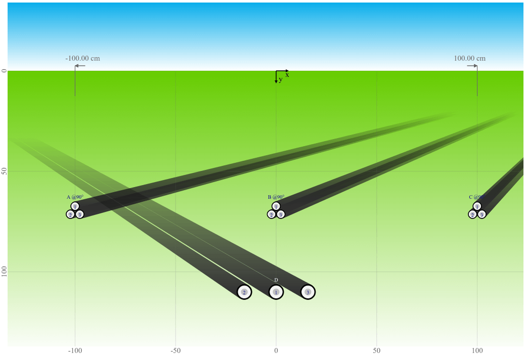
Next, we simulate systems A, B, and C crossing system D at different angles between 90° (perpendicular) and 0° (parallel laying, no crossing). The following figure shows a crossing angle of 90°.
The following graph shows the current ratings for systems A, B, and C with a fixed current of 520.6 A for system D. The ampacity is as expected higher for the outer systems A and C as compared to the center system B.
Current rating [A] as a function of crossing angle [°]
The following graph shows the maximum conductor temperature for system D with a temperature limit of 65°C for systems A, B, and C. The temperatures are as expected much higher than the 65°C without systems A, B, and C.
Maximum conductor temperature [°C] as a function of crossing angle [°]
With a decreasing crossing angle, the current ratings decrease as expected for systems A, B, and C (at fixed temperature) and the temperature increases for system D (at fixed current).
At a crossing angle of 0° (parallel laying, no crossing), the ampacity of system B (located in the center between systems A and C) is further reduced (from 325.2 A at a crossing angle of 1° to 301.4 A) due to a lot of mutual heating from three sides (left, right, underneath). The ampacity of the outer systems A and C however increases (from 341.2 A at a crossing angle of 1° to 392.7 A) because they are now further away from system D underneath and hence will experience less mutual heating. System D does not approach them like during crossing.
The same is valid for system D at a crossing angle of 0° (parallel laying, no crossing), which experiences less mutual heating and the temperature is lower than while crossing the other systems (84.0°C as compared to 87.1°C at a crossing angle of 90°). That is somewhat counter-intuitive because you might first think of just one single cable crossing another single cable (in which case the temperature is highest when laid in parallel and lowest when crossing at an angle of 90°).
We hope that this example helps you to get an understanding of the results you receive from your cable crossing simulations. If your results seem counter-intuitive at a first look, it might help to adjust the crossing angle in order to get a better understanding of what is going on. Of course you're always welcome to get in contact with us if you have any doubts about the validity of the simulation results.