Based on an example, the influence of the spacing between crossing systems on the cable rating is discussed and the limitations of the calculation method are outlined.
Posted 2021-04-26
Categories:
User guides
When doing a crossing calculation we typically have the situation that new systems are crossing an existing heat source, like a heat pipe or existing cable system. When adding multiple cable systems, special attention needs to be directed to the spacing between these systems. Sometimes, the results are not obvious at first glance and in order to better illustrate the underlying effect, we will discuss it on the following example.
To show you the effect of the spacing between systems on the cable rating, we use an example where we calculate systems A, B, and C (three cables in trefoil arrangement) crossing an existing system D (three cables in flat arrangement with a constant spacing of 8 cm, i.e. 15.8 cm center to center). The existing system D has a predefined rating which must be respected and therefore a fixed current of 400 A is set. The distance between systems A, B, and C is not predefined and thereforewe are investigating two cases with a spacing of 100 cm (left) and 50 cm (right) respectively.
| Crossing preview with 100 cm system spacing | Crossing preview with 50 cm system spacing |
|---|---|
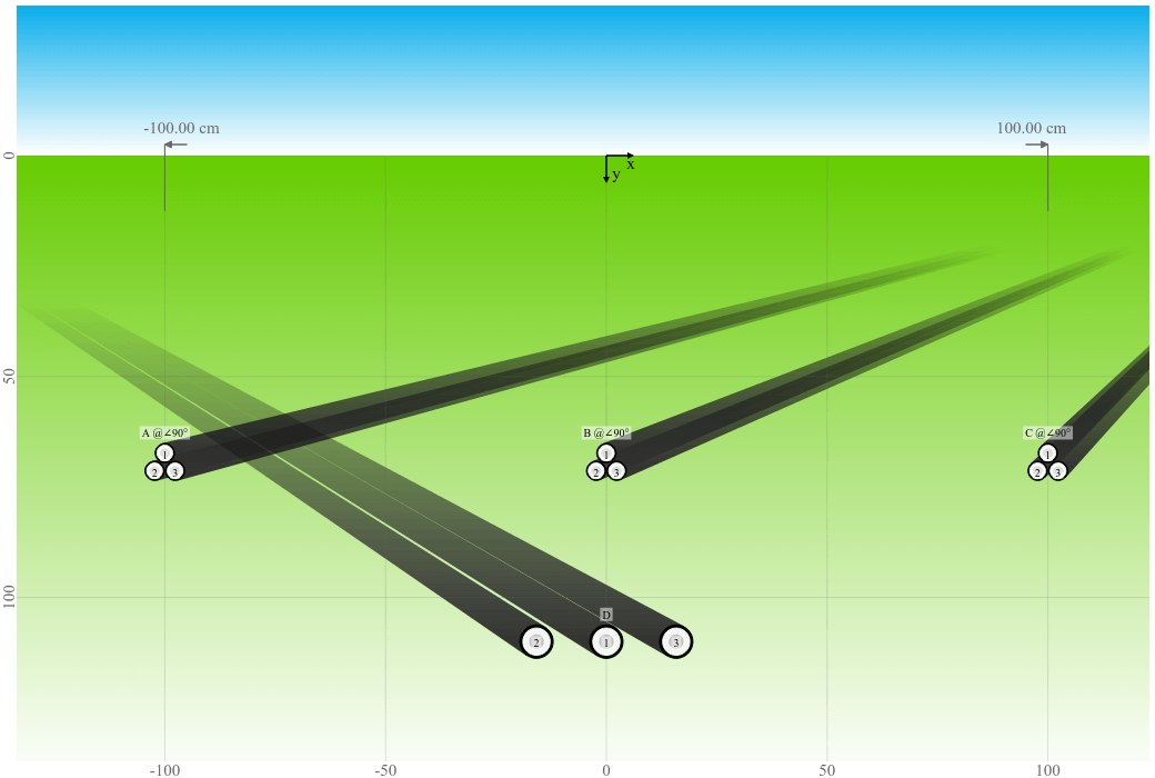 |
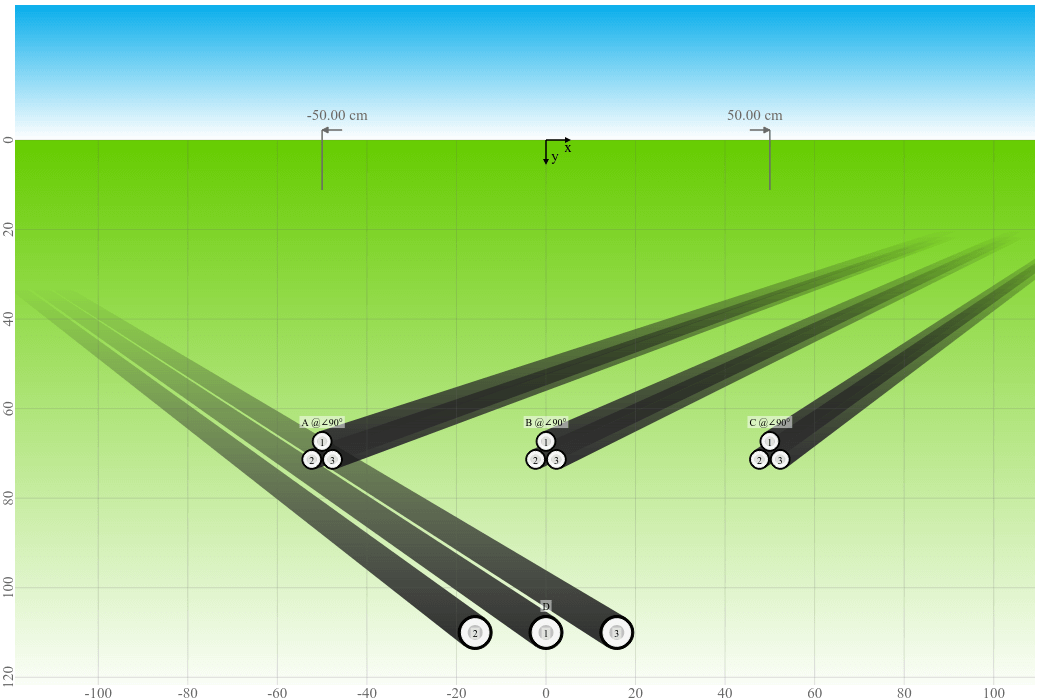 |
When systems A, B, and C are simulated with a fixed current rating of 400 A, it can be noticed that the temperature of systems D is as expected higher with a decreasing spacing between the systems.
| Spacing | System A @ 400 A | System B @ 400 A | System C @ 400 A | System D @ 400 A |
|---|---|---|---|---|
| 100 cm | 67.0 °C | 70.4 °C | 67.0 °C | 71.2 °C |
| 50 cm | 76.5 °C | 81.9 °C | 76.5 °C | 72.1 °C |
When systems A, B, anc C are simulated with a fixed temperature of 65 °C, the temperature of system D is somewhat unexpectedly lower with a decreasing spacing between the systems. This can be explained with the fact that the current rating is also decreasing with the decreasing spacing between systems A, B, and C.
| Spacing | System A @ 65 °C | System B @ 65 °C | System C @ 65 °C | System D @ 400 A |
|---|---|---|---|---|
| 100 cm | 391.4 A | 373.0 A | 391.4 A | 69.6 °C |
| 50 cm | 364.6 A | 221.9 A | 364.6 A | 65.7 °C |
Let's try to explain in more detail how the crossing method works, which is based on the IEC standard 60287-3-3.
The conductor temperature rise along the route of the rated cable, caused by the influence of the crossing heat source, may be calculated using Kennelly’s principle. The temperature rise is maximum at the crossing point and decreases with the distance $z$ from it. As a consequence of the varying temperature rise along the cable length, a longitudinal heat flux is generated in the conductor, which leads to a reduction in the conductor temperature rise at the crossing, compared to the case when this longitudinal flux is ignored.
The maximum permissible current in the cable to be rated, taking into account the presence of a crossing heat source, is obtained by multiplying the steady-state rating of the cable, without the crossing heat source, by a derating factor $F_{red}$ related to the influence of the heat source: $$\sqrt{- \frac{\Delta \theta_{0x}}{- \Delta \theta_{d} + \Delta \theta_{max}} + 1}$$ $\Delta\theta_{0x}$ is the temperature rise of the conductor(s) of the rated cable, due to crossing heat sources, at the hottest point in the cable route: $$\sum\limits_{h=1}^{k_X} T_{mh} \cdot W_h$$ $W_h$ are the losses and $T_{mh}$ is the mutual thermal resistance between the rated object and the crossing object with several crossings: $$\frac{\rho(e^{\gamma_X\Delta z}-1)}{4\pi} \sum\limits_{{v}=1}^{N_X} T_{mh_v}$$ There is a sum of $T_{mh_v}$ values, which are like slices. This $T_{mh_v}$ is again the mutual thermal resistance between the rated object and the crossing object with several crossings of one specific slice: $$\ln{\left(\frac{\left(L_{h} + L_{r}\right)^{2} + \left(\Delta z \nu + \operatorname{Abs}{\left(- z_{h} + z_{r} \right)}\right)^{2} \sin^{2}{\left(\frac{\beta_{h}}{2} - \frac{\beta_{r}}{2} \right)}}{\left(- L_{h} + L_{r}\right)^{2} + \left(\Delta z \nu + \operatorname{Abs}{\left(- z_{h} + z_{r} \right)}\right)^{2} \sin^{2}{\left(\frac{\beta_{h}}{2} - \frac{\beta_{r}}{2} \right)}} \right)} e^{- \Delta z \gamma_{X} \nu}$$ So it is an exponential function with respect to the distance from the hottest point.
For more details about the calculation method, please refer to our Jicable'19 puplication "Ampacity Calculation of Multi-System Cable Crossings at 40 MVA Frequency Converter Station Mendrisio" by D. Aegerter and S. Meier.
The additional heat from a crossing object will heat up the system under observation. This heat will "spread out" to the left and right of the system under observation. The temperature being highest at the crossing point and decreasing more and more further away from it. The faster it can decrease the better. The standard that over a distance of 5 m, the increase will be almost zero.
The standard has an Annex with the equations to calculate the distribution, but only for one system crossing one other system. The curve will look like a bell, like a Gaussian distribution. In the book "Rating of Electric Power Cables in Unfavorable Thermal Environment" by G. Anders, 2007, figure 3-9 shows an example of this curve.
Now when multiple heat sources are involved, the heat cannot decrease as quickly anymore and the curve would be wider and the decrease is slower. So it actually makes sense that you may see higher temperatures for 100 cm spacing instead of 50 cm spacing.
But there is a catch. When you spread out more and more, at some point, the systems become thermally independent and you should calculate the crossings separately. In between this, it is not really 100% accurately possible to calculate the temperature distribution precisely. The IEC only describes one system crossing one other system and they mention that for crossing several systems, the method is in general applicable too. That's how it is implemented in Cableizer. But due to this issue, the method is good for crossing of groups of cables, meaning they are not spaced far from each other. Crossing of spaced cables with another cable is not accurate. If you want to be more accurate, a finite element method (FEM) could be used. But then there are many other parameters which you will not know precisely and which affect the rating probably more than this.
It is not possible to give an exact guidande to what the distance of spacing between crossed cables is where Cableizer calculates the ampacities right. It depends on different factors. But the calculation is not per se false, but the accuracy will decrease with an increased spacing.