With the web-based cable calculation software Cableizer.com you can calculate the current rating of cables crossing external heat sources. It allows to calculate the current rating or temperatures of multiple cable systems crossing at any angle multiple other cable systems or heat sources. To our knowledge, Cableizer is the only commercially available software that allows to calculate the crossing of multiple systems with multiple other systems.
Posted 2018-01-20
Categories:
New feature
, Theory
, Validation
The IEC 60287-3-3 describes a method for calculating the continuous current rating factor for cables of all voltages where crossings of external heat sources are involved. The method is applicable to any type of cable and assumes that the entire region surrounding a cable, or cables, has uniform thermal characteristics and that the principle of superposition applies. The crossing heat source can be located either above or below the rated cable(s) with the crossing angle ranging from parallel to perpendicular.
The conductor temperature rise along the route of the rated cable, caused by the heat generated by the crossing heat source, may be calculated using Kennelly’s principle. The temperature rise is maximum at the crossing point and decreases with the distance z from the crossing. As a consequence of the varying temperature rise along the cable length, a longitudinal heat flux is generated in the conductor, which leads to a reduction in the conductor temperature rise at the crossing, compared to the case when this longitudinal flux is ignored.
The maximum permissible current in the cable to be rated, taking into account the presence of a crossing heat source, is obtained by multiplying the steady-state rating of the cable, without the crossing heat source, by a derating factor, DF, related to the heating due to the heat source.
The derating factor DF can be generalized for several heat sources crossing the rated cable by applying a superposition principle. In order to make this generalization, it is assumed that the point z = 0 is the position where the temperature of the rated cable is at its maximum. If the position of the hottest point can not be predetermined it may be necessary to perform the calculation at several points to ensure that the hottest point is found.
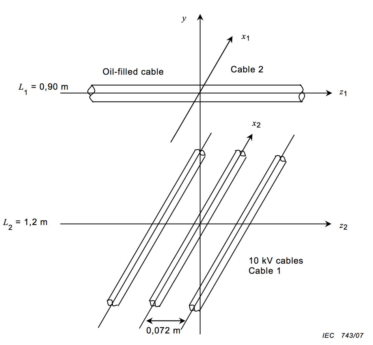
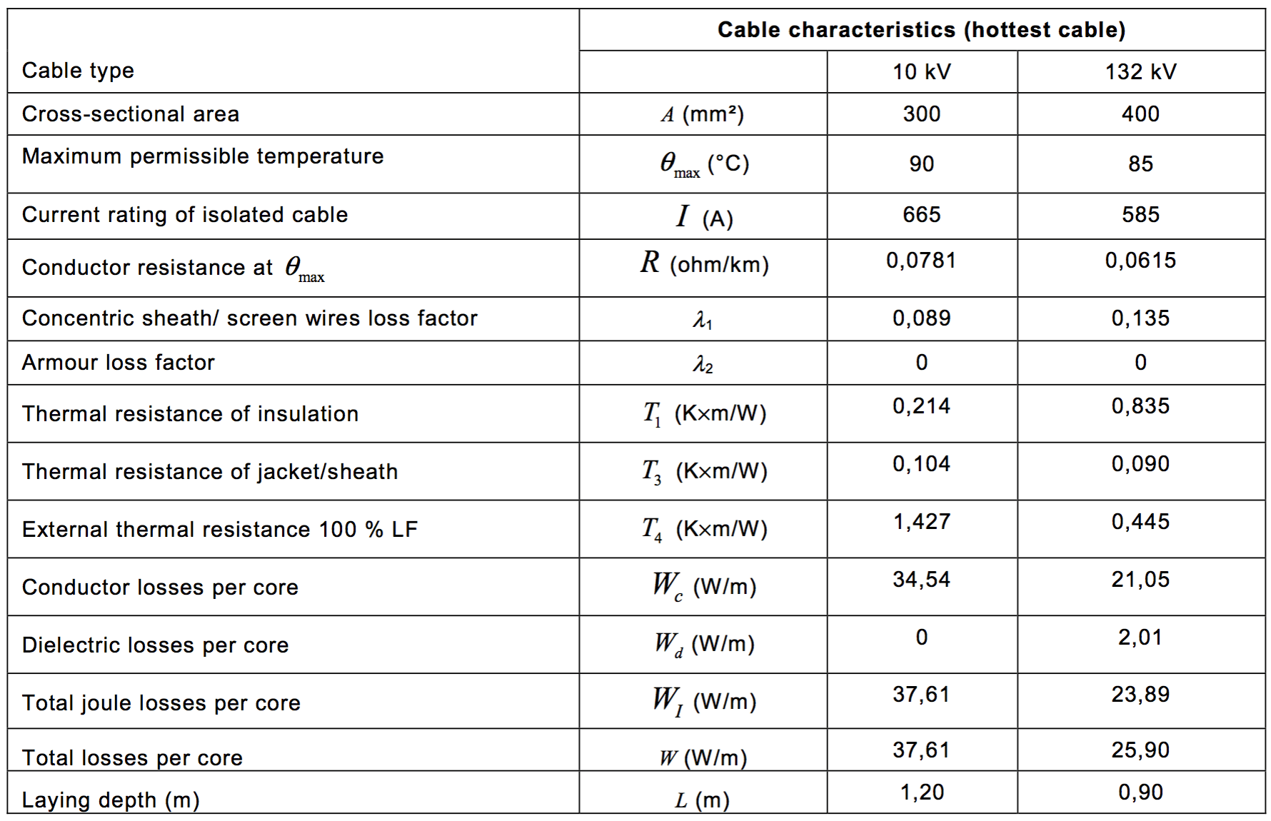
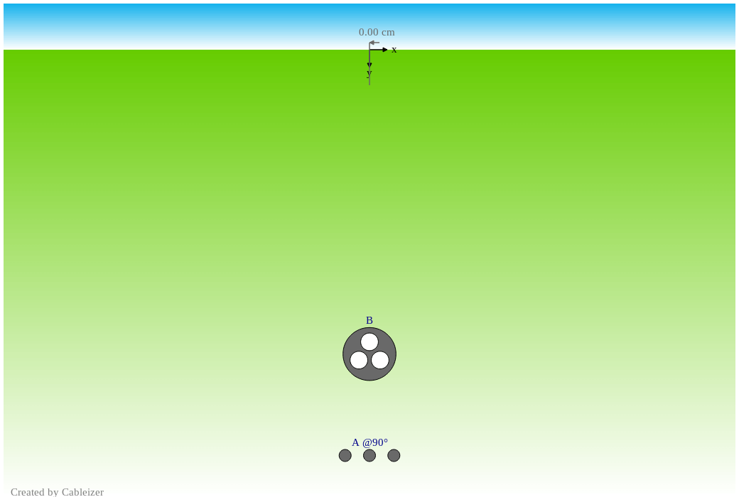
The following example is given in IEC 60287-3-3. The example is that of a 10 kV circuit of 300 mm2 Cu XLPE single-core cables with a maximum permissible temperature of 90°C, laid in flat formation (with a 0.072 m spacing) in 1.2 m depth and a 400 mm2 Cu 132 kV three-core oil-filled cable with a max. temperature of 85°C laid in 0.9 m depth. The ambient temperature is 25°C, the soil resistivity is 0.8 K.m/W and the crossing angle is 90°C (circuits are at right angles). The standard gives furthermore a table with loss factors, thermal resistances and losses
| Cable configuration | Cable and installation data |
|---|---|
 |
 |
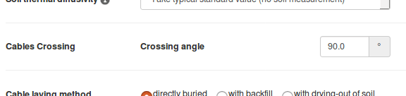
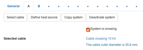
With Cableizer we first model both cables and then place them in the project editor as usual. Next you enter the crossing angle β on the "General" tab. Now you have to go to the crossing system (or systems in case there are more than one) and tick "System is crossing". Of course, Cableizer gives you an error if two systems would collide while crossing.
| Enter crossing angle in General tab | Select the crossing system(s) in the system tab(s) |
|---|---|
 |
 |
In the 2D preview you now see the crossing angle next to the corresponding system.
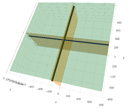
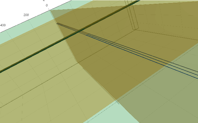
But Cableizer can do more: Just click on the link "preview in 3D" above the 2D preview and you will get a three-dimensional preview of the crossing situation. This is very helpful when you have multiple systems crossing. We use the widely used module plotly. It allows to turn and zoom the preview of your crossing situation.
| Preview in Cableizer in 2D | Preview in Cableizer in 3D | Zoom into preview in 3D |
|---|---|---|
 |
 |
 |
Using the method, the standard states that four iterations were necessary to get the derating factors of the two links when taking into account mutual thermal effects. The final result is as follows:
| Cable type | Derating factor |
|---|---|
| 300 mm2 XLPE 10 kV | 0.92 |
| 400 mm2 132 kV oil-filled | 0.85 |
However, during our development of the calculation method, we identified a systematic error in the standard's solution of this example. The calculation of the mutual thermal resistance for the right cable was not correct. The error was small but is repeated with each iteration and was therefore systematic. We informed the working group to correct this with the next edition of the IEC 60287-3-3.
The correct results are:
| Cable type | 1st iteration | 2nd iteration | 3rd iteration | 4th iteration | 5th iteration |
|---|---|---|---|---|---|
| 300 mm2 XLPE 10 kV | 0.8852 | 0.9200 | 0.9128 | 0.9149 | 0.9144 ≈ 0.91 |
| 400 mm2 132 kV oil-filled | 0.8258 | 0.8656 | 0.8541 | 0.8565 | 0.8558 ≈ 0.86 |
These values were reached by using the given values for loss factors, thermal resistances and losses. Based on our own calculations, the effective values for the two cables were slightly different. In order to compare with the results from the standard, we fixed the parameters to the given values.
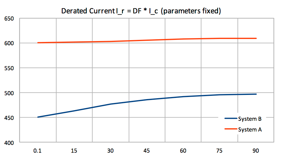
Now we calculated the derating factor and the derated current for different crossing angles between 0 and 90° using the given values for loss factors, thermal resistances and losses.
| Derating factor for different angles (IEC 60287-3-3) | Derating current for different angles (IEC 60287-3-3) |
|---|---|
 |
 |
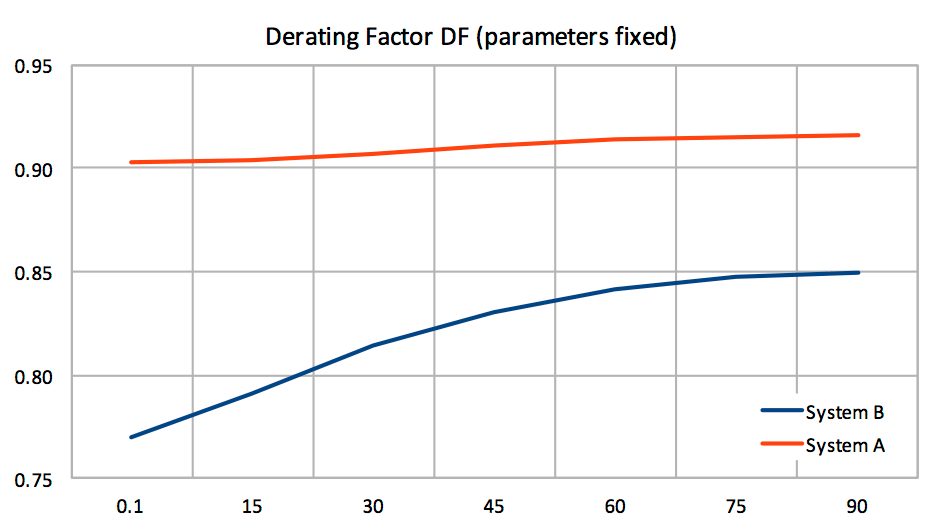
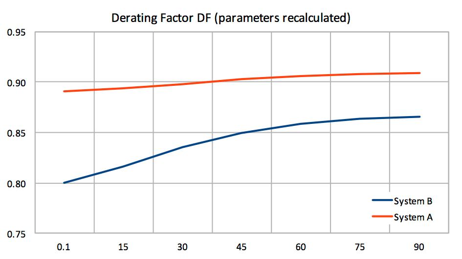
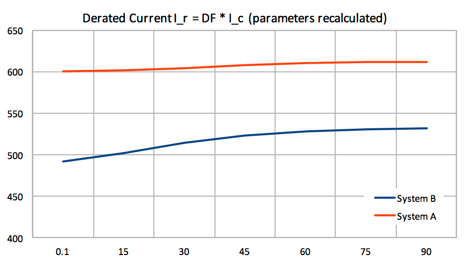
The thermal resistances and losses for the two cables calculated by Cableizer are not exactly the same as the given values in the standard. Additionally, Cableizer does recalculate the losses for the changed conditions (temperatures of conductor, screen and so on). So the derating factor and the derated current for different crossing angles between 0 and 90° calculated with Cableizer are different from the results above.
| Derating factor for different angles (Cableizer) | Derating current for different angles (Cableizer) |
|---|---|
 |
 |
Note that because the arrangement is symmetric, the result is the same for a crossing between 0 and -90° but this is not the case if there were multiple systems because the position z where the temperature is at its maximum will change. Our calculation weights the losses with the distance to each crossing heat source and automatically calculates this position.