This user guide describes how to define a heat source or a heat sink in Cableizer. The differences between a definition based on the dissipated heat or the surface temperature are outlined and explained.
Posted 2014-10-13
Categories:
User guides
In Cableizer, a heat source, such as a district heating pipe, is defined as having a positive heat dissipation, i.e. heat is dissipated from the heat source to the surrounding soil. In contrast, a heat sink, such as a water or cooling pipe, is defined as having a negative heat dissipation, i.e. heat is absorbed by the heat sink from the surrounding soil.
In the arrangement editor, click on the "General" tab and choose the calculation of buried cables. Heat sources, respectively heat sinks, can only be simulated with buried cables. They can be situated both inside or outside of an eventual backfill. Now click on a system tab of your choice and press the button "Define new heat source". You are now ready for entering the necessary heat source parameters, which are the center position, the diameter, and the heat dissipation or the surface temperature of the heat source.
Figure 1 shows the cable arrangement that is used to illustrate the behavior of a heat source system. The arrangement consists of a three-phase cable system placed in a common duct at a lying depth of 1m, with a heat source situated at a horizontal distance of 0.5m. All simulations are constrained such that the temperature of the conductors stays 90 °C.
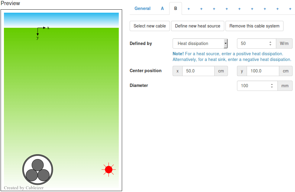
Fig. 1 Investigated cable arrangement with heat source
A definition by heat dissipation determines clearly whether it is a heat source or a heat sink. The following table (simulation inputs: heat dissipation and diameter, simulation outputs: ampacity and surface temperature) shows that the larger the heat dissipation of the heat source, the lower the allowed ampacity of the cable system. It should also be noted that the diameter of the heat source in this case does not influence the ampacity of the cable system (which only depends on the heat dissipation and the center position of the heat source). However, the diameter of the heat source influences the surface temperature of the heat source.
| Heat dissipation | Diameter | Ampacity | Surface temperature |
|---|---|---|---|
| -50 W/m | 100 mm | 757.3 A | 2.6 °C |
| 0 W/m | 100 mm | 693.4 A | 36.6 °C |
| 50 W/m | 100 mm | 622.4 A | 70.6 °C |
| 50 W/m | 200 mm | 622.4 A | 63.4 °C |
| 50 W/m | 50 mm | 622.4 A | 77.8 °C |
When defined by surface temperature, it depends on the temperature of the surrounding soil if it is a heat source or a heat sink. A heat source besides an unloaded cable system with a fixed surface temperature, might well act as a heat sink once the cable system is loaded. Looking at the heat dissipation in the simulation results indicates clearly whether it is a heat source or heat sink at that specific operating conditions. Looking at the following table (simulation inputs: surface temperature and diameter, simulation outputs: ampacity and heat dissipation), it can be noted that the ampacity of the cable system is increasing with a decreasing surface temperature of the heat source. Below a surface temperature of 36.6 °C, it will act as a heat sink. Be aware, that the diameter of a heat source has an influence on the ampacities of surrounding cable systems when you define a heat source by its surface temperature!
| Surface temperature | Diameter | Ampacity | Heat dissipation |
|---|---|---|---|
| 15 °C | 100 mm | 734.8 A | -31.8 W/m |
| 35 °C | 100 mm | 696.6 A | -2.4 W/m |
| 55 °C | 100 mm | 656.0 A | 27.0 W/m |
| 55 °C | 200 mm | 645.6 A | 34.3 W/m |
| 55 °C | 50 mm | 662.7 A | 22.3 W/m |