Induced voltage on out-of-service cables
In multi-circuit installations, it is common to take one cable system out of service while neighboring circuits remain loaded. Even though the “victim” circuit is de-energized, magnetic coupling from the energized circuits can induce a longitudinal voltage along the out-of-service cable (typically discussed for screens/sheaths and parallel metallic paths).
With the new WRK plot feature in Cableizer, you can now generate a route-based visualization of this induced longitudinal voltage directly at the end of a rating calculation.
The implementation is based on the work of Mikhail Dmitriev in his latest book 'High Voltage Cable Lines', excellent reading material for the engineer interested in cable technology.
Availability: only for multi-system route modules
The WRK plot is only available when your calculation contains multiple cable systems, because the purpose is to evaluate coupling between systems.
Therefore, this feature is only provided in modules that support multiple parallel systems along a route:
- Buried
- Trough
- Tunnel
If your project has only one system, there is no external inducer, so the WRK plot is not offered.
Where you find it in the workflow
After completing the rating calculation, Cableizer provides a modal window titled “Induced voltage on out-of-service cables”. In this window, you select which system is treated as the victim and generate the WRK plot for that system. You can repeat the process for other systems by selecting a different victim.
What the WRK plot shows
The generated chart contains two coordinated views:
-
Upper plot: induced voltage profile
- Induced longitudinal voltage in [V] plotted along the route position.
- Separate curves per victim conductor/phase label (for example R, S, T, etc.).
- The plot highlights end values to support quick assessment of worst-case induced voltage at the victim end.
-
Lower plot: parallel exposure overview
- A thick reference line marks the victim system section (start to end).
- Other active systems are drawn along their defined start/end positions.
- Each system is placed at an indicative vertical level based on its average spacing to the victim (from the installation geometry), helping identify dominant contributors.
Input parameters (per system)
The WRK inputs are defined per system and are intentionally very similar to the existing magnetic field calculation inputs in the EMF modal window. However, unlike EMF, the WRK result is computed for one selected victim system and depends on all other systems, because the induced voltage is only accumulated where other systems run in parallel with the victim.
| Parameter | Meaning | Typical input guidance |
|---|---|---|
system |
Cable system identifier and configuration summary (as shown in the WRK modal list). |
Select the system you want to evaluate as the victim (out-of-service) using the corresponding Go button.
Review the description to ensure you are choosing the correct circuit (especially in projects with similar cable types).
|
Ic[A] |
Load current magnitude of the system. | For inducing systems, use the expected operating current for the scenario of interest (normal load, contingency, seasonal case, etc.). For the victim system, the value is typically not critical unless you are also modeling it as an active source (normally the victim is out of service). |
f[Hz] |
System frequency used for coupling evaluation. | Enter the actual operating frequency of each system. This is important when multiple systems operate at different frequencies, because the relative phase relationship changes over time. |
αf[°] |
Phase shift of the system current relative to a reference. |
Use 0 to represent “in phase” with the reference.
For different-frequency systems, any phase value from 0 to 360° may be used to represent the assumed phase offset.
Keep values consistent if you compare scenarios.
|
loadflow[1 / -1 / 0] |
Load flow direction and activation state:
1 = positive direction, -1 = negative direction, 0 = deactivated (excluded from induction).
|
Set 0 for systems that should not contribute to induction in the considered scenario.
Ensure at least one system is set to 1 or -1, otherwise there is no energized source and no induced voltage can be computed.
Use the correct direction when studying cancellation or reinforcement effects between circuits.
|
start / end[m] |
Route position limits of each system along a common reference coordinate. Only overlapping sections (parallel exposure) contribute to induced voltage on the victim. | Use the same stationing reference for all systems (e.g., from the same route origin). Check that victim and inducing systems overlap where they physically run in parallel. If an inducing system only overlaps partially, only that segment will contribute in the WRK plot. |
Calc. (Go) |
Runs the WRK calculation for the selected victim system and generates the plot. |
Click Go on the row of the system you want to treat as the victim.
Repeat for other systems if you need induced voltage plots for multiple potential victims.
|
Note: At least one system must have a load flow of 1 or -1. If all systems are set to 0, there is no energized source and no induced voltage to compute.
Considerations
How Cableizer calculates the induced voltage
The WRK tool follows a practical electromagnetic coupling approach consistent with power-frequency cable engineering. It is designed to be transparent for engineering use without requiring software-level details.
1) Conductor modeling as filament currents
Each conductor in the inducing systems is represented as a filament current at its geometric position derived from the installation layout. This is a standard approximation to evaluate magnetic coupling based on conductor spacing and arrangement.
2) Magnetic coupling using Biot–Savart-based mutual inductance per unit length
Cableizer evaluates the magnetic coupling from the inducing systems to the victim using a Biot–Savart-based mutual inductance per unit length approach, including an earth-return approximation to account for practical return-path effects. In engineering terms: smaller separation and longer parallel exposure increase coupling and therefore induced voltage.
3) Multi-system superposition with frequency, phase shift, and load flow
Contributions from multiple inducing systems are combined consistently, considering each system’s:
- Current magnitude Ic
- Frequency f
- Phase shift αf
- Load flow direction (1 or -1) or deactivation (0)
4) Parallel exposure defined by start/end overlap
The induced voltage is accumulated only over the route sections where an inducing system and the victim system overlap. If there is no overlap, that inducing system has no contribution on that portion of the victim route. If overlap is partial, only that segment contributes.
5) From induced voltage gradient to route-based induced voltage
For each victim conductor/phase label, Cableizer forms a longitudinal induced voltage contribution per unit length along the route (conceptually V/m), then integrates along distance to obtain the induced voltage V as a function of route position. This produces the upper plot’s voltage profile and the reported end values.
Typical use cases
- Safety assessment for maintenance work on an out-of-service system (induced voltages on screens/sheaths or parallel metallic parts).
- Comparing alternative routing options (change separation, reduce parallel length, adjust arrangement).
- Identifying dominant inducing systems by combining the lower plot (exposure + spacing) with the upper plot (voltage build-up).
Practical tips for reliable results
- Verify start/end positions carefully; WRK is highly sensitive to parallel overlap length.
- Set the correct load flow direction for each energized circuit.
- If multiple frequencies exist, set f and αf intentionally (do not rely on defaults if phase relationships are known).
- If a system should not contribute, set load flow to 0 rather than forcing current to zero.
Example
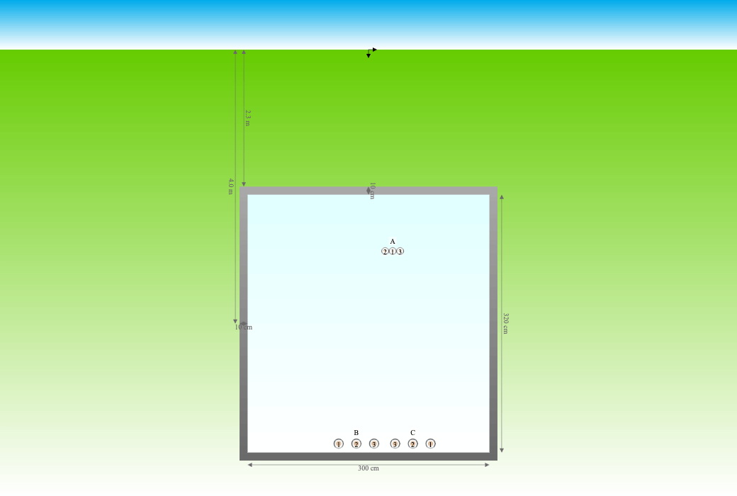
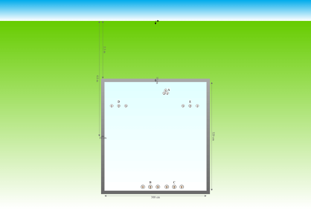
Let's show an example with a total of five 220 kV cable systems of different design in a channel. This is an actual ongoing project in the Swiss alps where Cableizer was used to do the cable engineering from cable design, rating calculation, drum dimensioning, cable pulling, mechanical forces and with this latest tool the induced voltage on cables being worked on.
The arrangement consists of two systems of 2500mm2 Cu cables in ducts at the bottom of the tunnel and three systems of 400mm2 Cu cables directly in air at the ceiling of the channel.
| Arrangement case 1 | Arrangement case 2 |
|---|---|
 |
 |
The ambient temperature $\theta_a$ is 10°C, the thermal resistivity of the rock is $\rho_4$ is 1.0 K.m/W
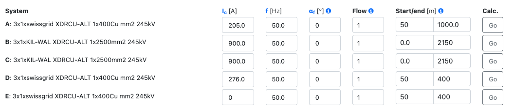
The calculation was done for two different systems:
- We calculate the induced voltage on the left system installed in ducts on the floor. This will be installed after energization of the other new system to the right. In addition an existing older 220 kV system is still active in the upper section of the channel. The new systems on the floor will carry high currents, are located close to each other, and the arrangement is flat which causes significantly unequal induced voltages.
- In a second phase, three new systems will be installed in the upper section of the channel and they replace the existing older system. We calculate the induced voltage on the right upper system which will be installed after energization of all other systems.
For the input data the maximum possible operating currents as given by the operator were used.
Case 1: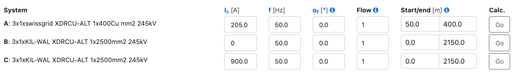
The resulting plot with the induced voltages is shown for the two calculated cases:
| Case 1 | Case 2 |
|---|---|
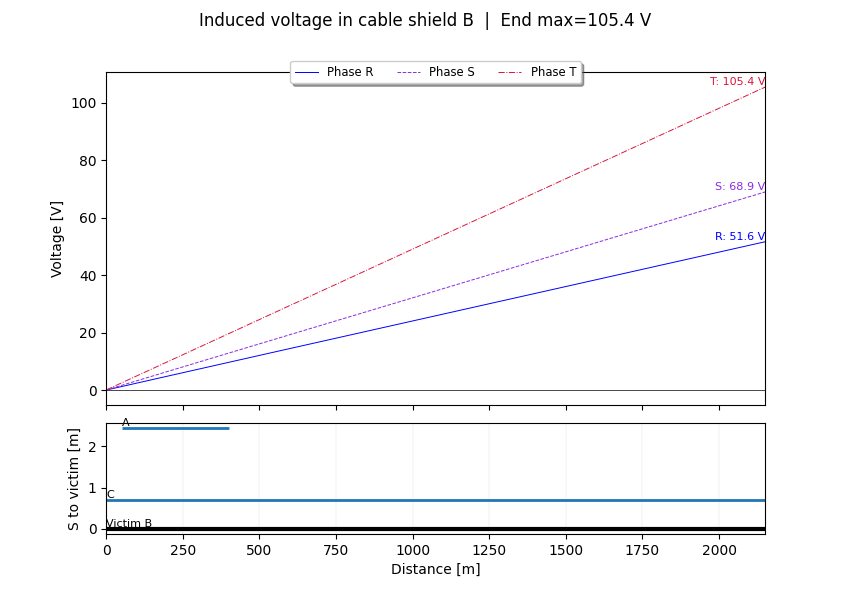 |
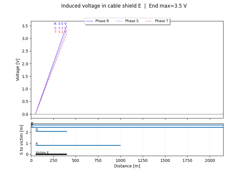 |
Reference
High Voltage Cable Lines by Mikhail Dmitriev. Porto, Portugal, 2024. 690 p.
This book explores the design, construction and operation of alternating current cable lines rated from 6 to 500 kV, consisting of single-core or three-core cables with XLPE insulation. It is intended for employees of design organizations and power grid companies, as well as university students.