DC Fast Chargers are designed to charge electric vehicles quickly with an electric output ranging between 50 kW – 120 kW, like the Supercharger from Tesla. At a typical 400 volts, this results in a current of 300 amps. A new target is 350 kW resulting in a current of almost 900 amps. For this, a new approach is needed for the DC supply cables.
Posted 2017-01-14
Categories:
New feature
, Theory
, Validation
Earlier this year, we had been contacted by two separate cable manufacturers regarding this issue of a new generation of DC Superchargers. They have both been contacted by manufactures for DC charging stations with questions about the design of high current DC power cables needed for the next generation of powerful charging stations up to 350 kW at a voltage level of 400 to 450 V.
There exist insulation materials that can be used at operating temperatures way beyond 90°C like for XLPE but this alone is not sufficient to come up with a cable with sufficient capacity while still being flexible.
Two new approaches were considered:
Cable rating methods for cables with internal cooling had been described in earlier technical publications where it was used for HV cables with cooling of the oil circulating in the center of the conductor. So technically, this method could be adopted and used for LV DC cables. However, the design of such small cables with internal cooling poses a far greater problem than the rating calculations would. The cooling fluid would need to run in a very small pipe that must be flexible and withstand thousands of bending cycles and have a low thermal resistivity to be effective. The fluid needs to circulate which calls for a special construction on one end where it leaves the cable to flow through a pump while at the other end, the fluid would pass from the plus phase to the minus phase. Due to these and other challenges, the manufacturer decided to keep the questions of cable rating on hold.
Regarding the second approach, we discussed the possibility to calculate 4 cables in a common duct which is not covered by IEC 60287. Cableizer agreed to implement a calculation method that is capable of calculating the ampacity of four cables in a common buried duct. In March 2016 it was added to our software and is since available to all users.
Our implementation even allows set a frequency >0 Hz resulting in the same set of equations as for 16.7 Hz railway systems where the two phases are 180° phase-shifted. Calculation of the magnetic fields is also possible for DC and AC 180° systems
For comparison, a calculation with a simple 1-kV-cable was done. The cable has a conductor with 70 mm² aluminium round solid with a DC resistance of 0.568 Ω/km, a XLPe insulation with a thickness of 1.05 mm, a LDPE jacket with a thickness of 1.95 mm, there is no screen, sheath or armour. The cable is laid in a PE duct with an inner diameter of 55.8 mm and an outer diameter of 63.0 mm in a laying depth of 500 mm to the center of the duct. For the simulation, the system shall have a frequency of 50 Hz which allows for calculation of the 3-phase system (the AC resistance only changes by a couple of ‰)
| Phases | Load | Current | Losses | Temp. in duct | Magnetic field at surface | AC resistance |
|---|---|---|---|---|---|---|
| 1 x 1 | 254.4 kVAA | 254.4 A | 1 x 36.8 = 36.8 W/m | 61.4°C | ≈ 100 µT | 0.5681 Ω/km |
| 1 x 2 | 201.2 kVA | 201.2 A | 2 x 23.0 = 46 W/m | 66.1°C | ≈ 2 ... 3 µT | 0.5683 Ω/km |
| 1 x 3 | 301.7 kVA | 174.2 A | 3 x 17.2 = 51.7 W/m | 68.6°C | ≈ 2 ... 3 µT | 0.5684 Ω/km |
| 2 x 2 | 312.1 kVA | 312.1 A (2 x 156.1 A) | 4 x 13.8 = 55.4 W/m | 70.2°C | < 0.2 µT | 0.5682 Ω/km |
| Approximate temperature field for 1 x 2 phases | Approximate temperature field 2 x 2 phases |
|---|---|
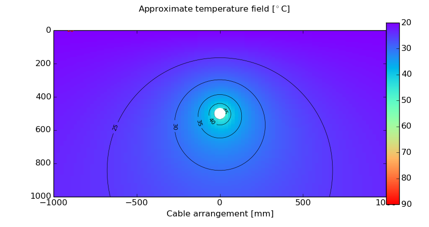 |
 |
| Magnetic field for 1 x 2 phases | Magnetic field for 2 x 2 phases |
|---|---|
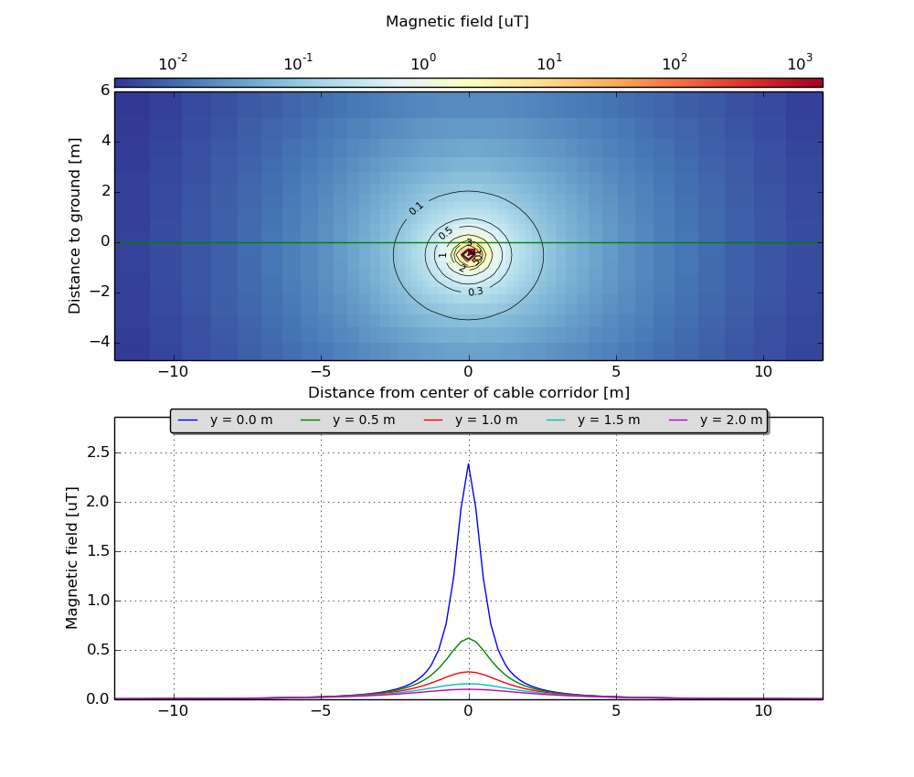 |
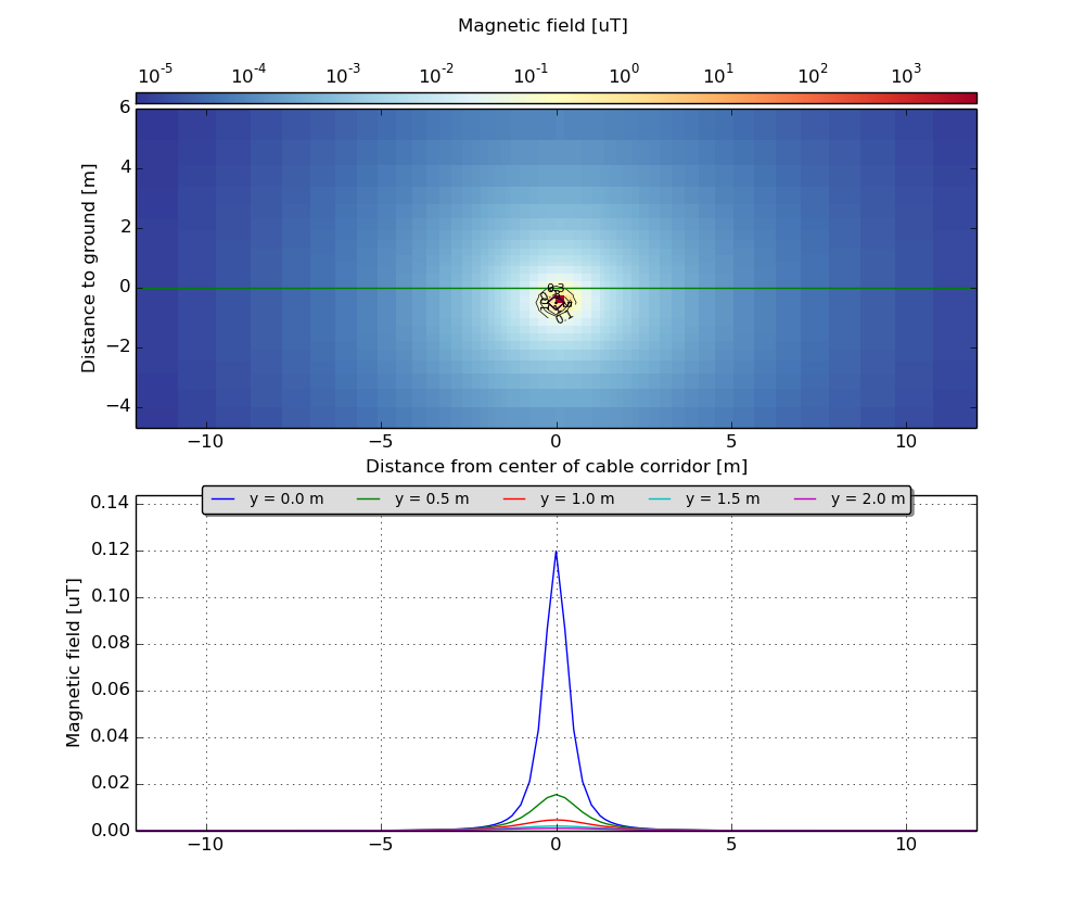 |