With Cableizer you can now calculate the thermal rating in J-tubes and risers.
Posted 2021-03-19
Categories:
New feature
The heat transfer through the riser or J-tube air section is calculated considering convection and radiation between the cable surface and the inner duct surface, the conduction through the duct, and convection and radiation between the outer duct surface and ambient air plus optionally solar radiation and wind.
We implemented four different analytic 2D calculation methods based on the following technical publications:
The first method is an empirically derived method and was published by ERA in 1988. The cables had outer diameters between 75 and 130 mm and the tubes between 160 and 400 mm. For other values, the results must be used with caution. The method is intended for use with J-tubes which are sealed at the top. The continuous rating is calculated by recognizing that under steady state conditions, the permissible heat flux across each radial component must be the same. Inherent within the balanced permissible heat flux statement is the assumption that minimal heat is produced within the armour and sheath which is a further limitation of this rating approach.
The second method is an analytical method proposed by R.A. Hartlein and W.Z. Black in 1983. It is based around a thermal network model and is more general in its applicability than the ERA empirical method. It considers tubes which are both open and sealed at the top. The ladder network for the cable is akin to the network layout within IEC 60287-2, with the temperature difference between two radial positions being given as Δθ = qT where q is the heat flux passing through the region which has a thermal resistance T.
The third method was published by G.J. Anders in 1996 and is an extension of the pioneering work by Hartlein and Black which missed formulae for computation of heat transfer coefficients under certain conditions and required assumptions which were sometimes incompatible with typical cable-riser geometry. The paper by Anders updated the work of Hartlein and Black by redefining the mathematical model and supplementing information lacking in their work. Comparison of both models was made and reported in a previous paper by Anders, published 1995. This method is used by our competitor Cymcap.
The fourth method is an analytical method proposed by R.D. Chippendale et al. in 2017 more in line with IEC 60287 approaches. Three component models are used, one for each of the three thermal sections: Central air section with the section below sea level before and the section with individual phases after. The results obtained demonstrate that a 2D approximation is acceptable for cases where the length of the tube air section is greater than 10 m. For lengths less than this, the use of the 2D methods becomes conservative and a 3D calculation is recommended, particularly for wind farm export cables with large conductor sizes.
Underground power cable systems are often connected to overhead lines at overhead transition towers where the cables pass short sections of protective ducts or channels. This installation with a protective guard is often referred to as a riser.
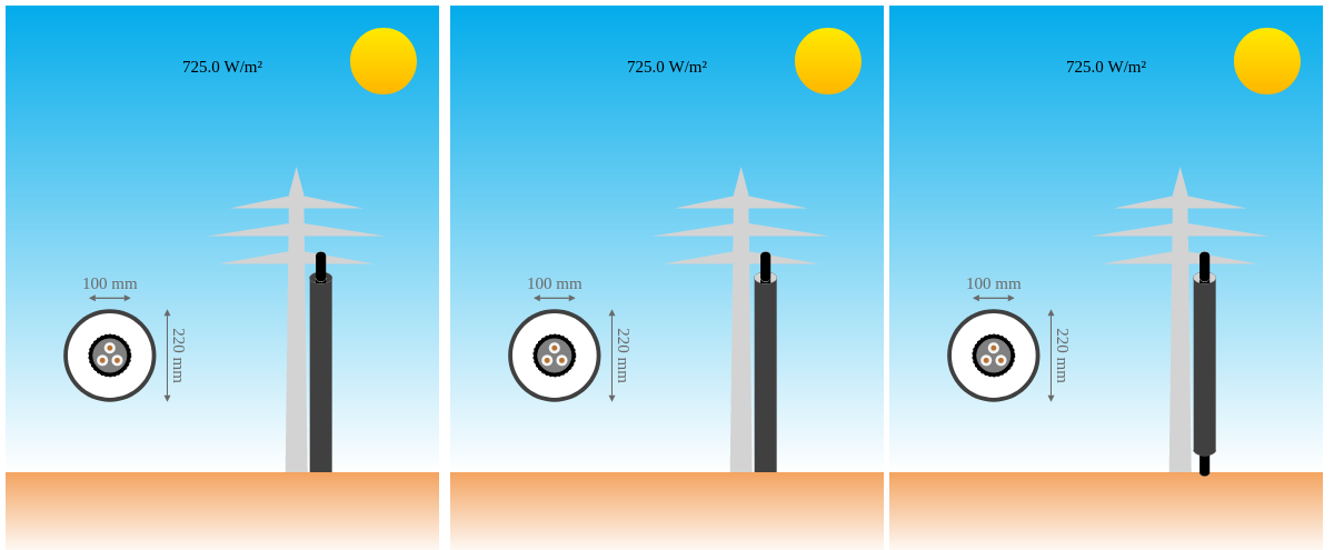
The cable(s) and the riser form a vertical annulus, concentric bodies with much greater length than diameters. If the temperature of the cables(s) or the riser inner wall surface is different from the ambient air temperature, natural convection occurs in the annulus gap. The Nusselt number to calculate the convective heat transfer coefficient between object and gas (air) $h_{conv_{og}}$ and between gas and inner duct wall $h_{conv_{gd}}$ depends on the way the riser is constructed and how the air can flow. The riser can be open at both ends, open at the top and closed at the bottom, or closed at both ends as shown below.
The calculation of the convective heat transfer coefficient $h_{conv_{da}}$ between the outer duct wall and the ambient air considers natural and forced convection or both depending on the wind speed.
Increasing numbers of offshore wind farms are under construction or in operation in European, American, and Asian waters. The correct sizing of high voltage cables, both within turbine arrays and for export systems is critical. The international standard IEC 60287 does offer analytical methods to predict the thermal rating of onshore cable installations but lacks methods to calculate the section of cable in the protective J-tube between the sea floor and the offshore platform, as well as for installations in cable protection systems (CPS). They can become the limiting factor for the overall circuit rating.
A typical J-tube layout is comprised of three sections as shown below:
