Offshore cable protection systems (CPS) need to be carefully modelled in order avoid failure of subsea power cables due to overheating caused by inadequate heat dissipation. We discuss what guidelines exist for this particular environment and which calculation methods you should use in Cableizer.
Posted 2021-03-11
Categories:
User guides
The cable protection system (CPS) protects subsea power cables from damage caused by fatigue, overbending of the cable, and mechanical impacts. The CPS is located between an offshore foundation such as a J-tube or wind turbine and provides protection until the cable reaches an area of burial.
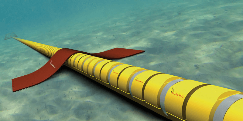
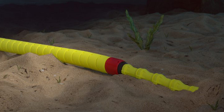
As shown in the above illustrations, the CPS is like a duct, either filled with water or with silt. In both cases, the medium is not freely moving along the CPS but is standing still. Three different cases can be considered:
All three cases are covered using the equations to calculate the thermal resistance $T_{4i}$ inside a duct. Note that we don't add the thermal resistance of the solid duct filling to $T_3$, the thermal resistance of the cable jacket, as proposed by CIGRE but instead to $T_{4i}$, the thermal resistance of the medium inside the duct, which is where it actually belongs to. Of course we consider the number of cables/conductors inside the duct. We have a difference to the principles of IEC when considering the solid duct filling: We don't consider the cables to be concentric inside the duct but that the thermal resistance is calculated for an eccentric arrangement with the cables laying on the bottom of the duct.
Our method for ducts filled with solid material even allows for the use of cyclic rating methods considering the expansion and contraction of the heat waves to begin at the cable surface inside the duct.
Often, the CPS is not at all or only partially buried as shown in the above illustrations. If this is the case, it is not possible to calculate with the IEC method.
CPS is buried - use the buried cable module and place your cables in a duct, with the dimensions and materials corresponding to those of the CPS.
CSP is not or only partially buried - this calculation is currently not possible in Cableizer. In the future, it will be implemented for the subsea cable module and the non-IEC methods. But unfortunately, it is currently not yet possible to select ducts in the subsea cable module.