Phase splitting can be used to drastically reduce the magnetic fields of buried power cables. Also, the conductor cross-section can be less than half because the current is only half per split system and it can give a partial redundancy of about 60% or even more in case of a cable failure on one split system.
Posted 2016-06-26
Categories:
Plots
, Theory
If you have a high current cable system, the magnetic fields directly above the cable route may reach values above 100 µT, which is the limit of exposure for the general public according to ICNIRP at 50 Hz. Some countries like Switzerland, Italy, Russia, Netherlands and others have even lower limits for exposure. If you need to lower the magnetic fields, you may add ferromagnetic shielding plates on top or around the cables, which are extremely costly. Another option is adding compensation loops on top of the cables but the reduction is quite limited and difficult to calculate correctly. Trefoil laying arrangement is better than flat arrangement and touching better than spaced. However, touching and trefoil reduces the ampacity because of higher mutual heating. And there is the option of compensation through parallel systems.
If there are one or several parallel cable systems with known typical direction of load flow, the magnetic field can be compensated significantly by an optimized phase arrangement of the systems against each other. For two systems, the optimal phase arrangement is point-symmetric in case of identical direction of load flow and axially symmetric for opposite direction of load flow. But what if you don't have a second system?
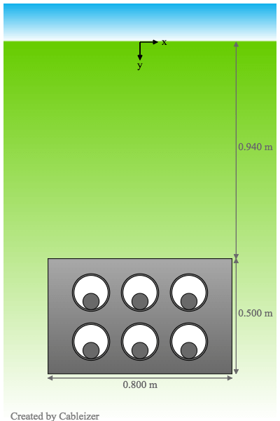
In order to significantly reduce the magnetic field at all time, one may use phase splitting. Each phase R, S and T will consist of two cables. These six cables are laid in a point symmetrical arrangement. In order to carry the same load, the cross section of the cable conductor can be less than half because the current is split and the mutual heating of 6 cables at 50% is lower than for three cables at 100%.
The cost for the cable system will of course be higher than before, but the grid operator gains another advantage in availability: a partial redundancy. In case of a cable fault, the three cables of the faulty half system can be disconnected and the remaining three cables will carry approximately 60-70% of the load, depending on the laying arrangement and conditions.
Cableizer offers a feature to select phase splitting for buried cables directly buried or in separate pipes by simply setting a tick mark for the corresponding system. In case of defined laying arrangements such as flat horizontal, flat vertical, trefoil apex up, trefoil apex down, the second system will be laid accordingly with optimized phase arrangement by simply entering the desired distance between the two half-systems. In case of individual laying, the user may place all six cables individually - point symmetry should be maintained.
You can see the effects of the phase splitting in the following example calculations. The system with 3 cables uses 1200 mm2 Al for 1000 amps and the one with 6 cables only 500 mm2 for 2x500 amps. And using 800 mm2 Al for the 6 cables will significantly lower the losses by almost 30% which pays off in the long run.
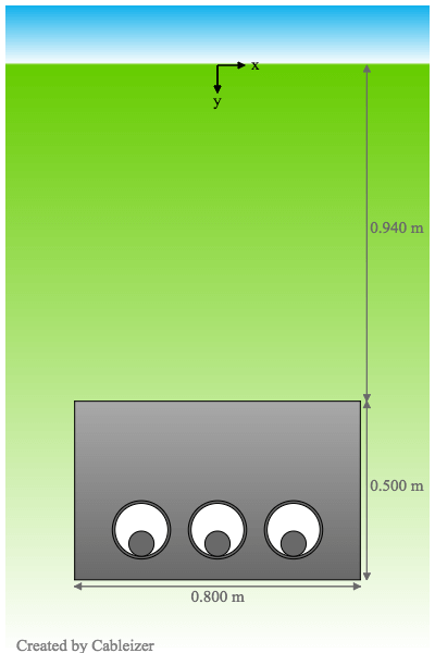
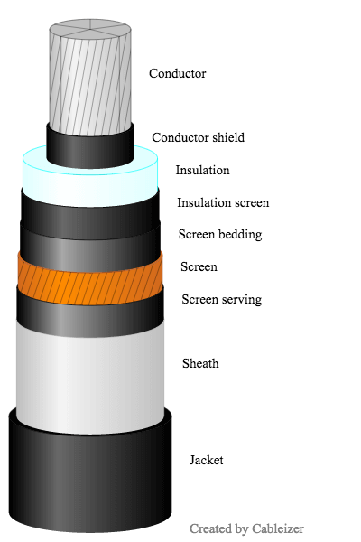
The following example was calculated with one 50 Hz 110-kV-cable system laid flat in a ductbank with an ambient temperature of 20°C, a soil thermal resistivity of 1.2 K.m/W and a thermal resistivity of the ductbank of 0.8 K.m/W. The cables are typical 110-kV-cables with aluminium conductor, an XLPE insulation with a thickness of 1.6/13/0.8 mm, an aluminium multi-layer sheath with copper wire screen, and a PE-sheath with a thickness of 4.1 mm.
| Laying arrangement without phase-split | Laying arrangement with phase-split | XLPE cable milliken Al 1x1200mm2 110kV |
|---|---|---|
 |
 |
 |
Here you can download all four reports, namely for case 1: ![]() | case 2:
| case 2: ![]() | case 3:
| case 3: ![]() | case 4:
| case 4: ![]()
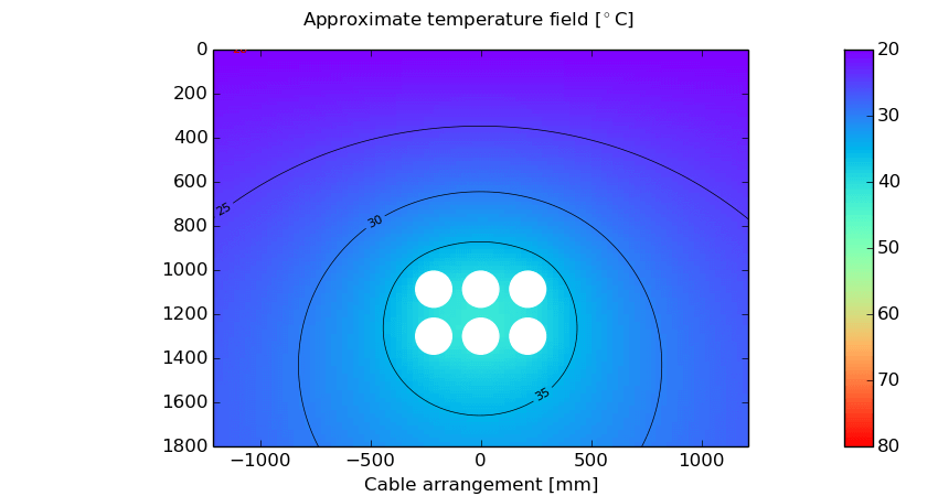
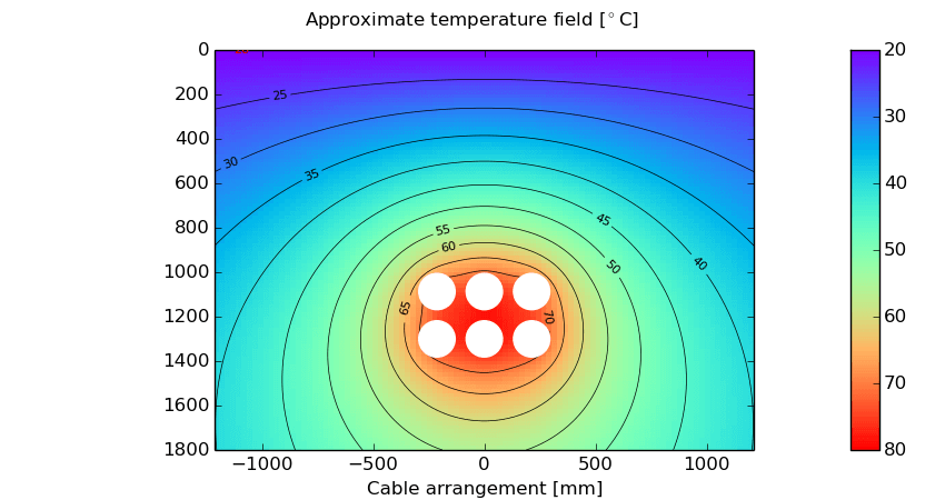
| Approximate temperature field without phase-split (1200 mm2) | Approximate temperature field with phase-split (1200 mm2) |
|---|---|
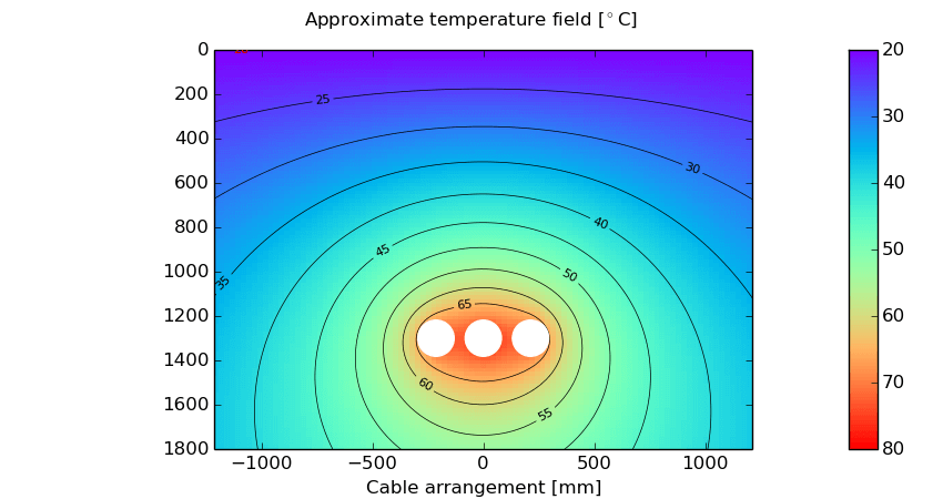 |
 |
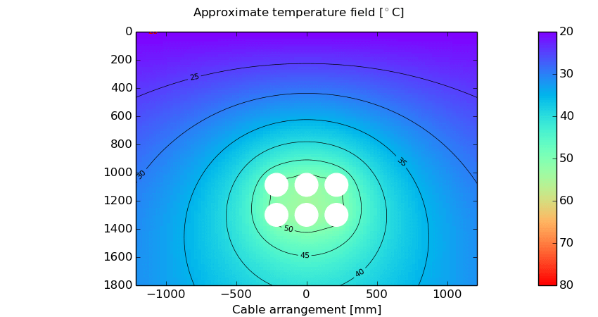
| Approximate temperature field with phase-split (500 mm2) | Approximate temperature field with phase-split (800 mm2) |
 |
 |
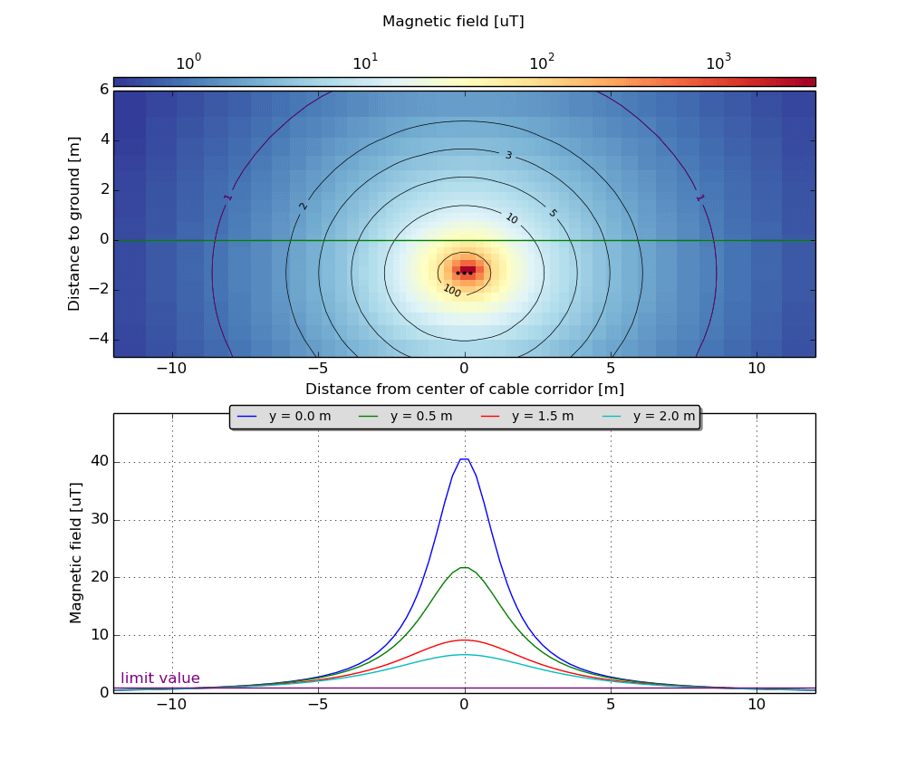
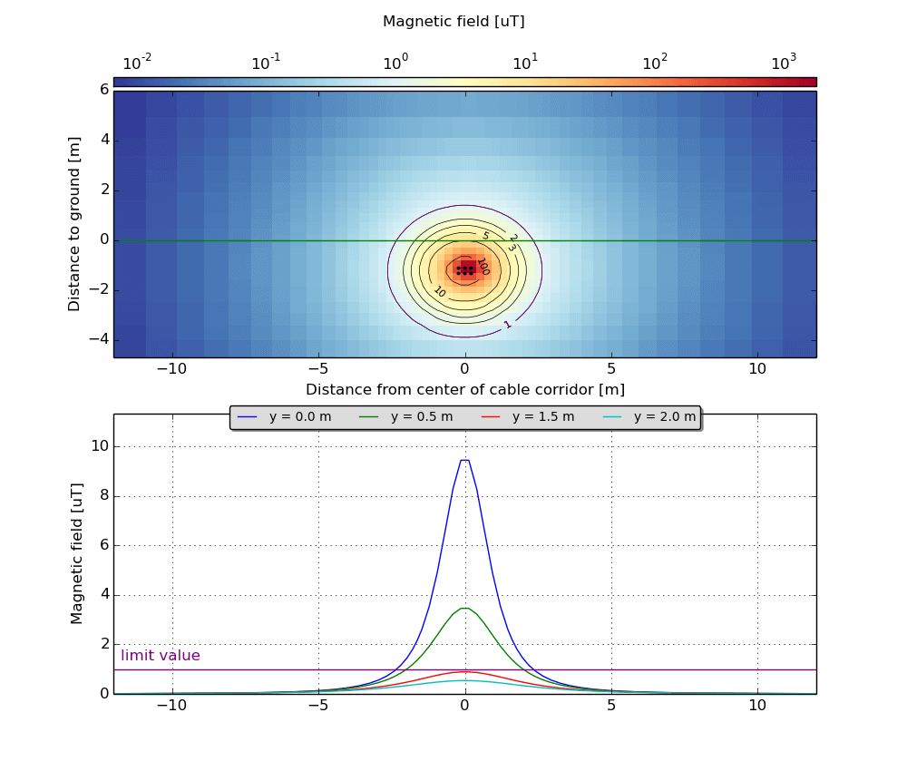
For 3 cables at 1000 A, the magnetic field is >10 µT up to 3 m to the left and right of the line axis and more than 40 µT directly above the line axis. For 6 cables at 500 A, the magnetic field is below 10 µT everywhere at ground level.
| Magnetic field without phase-split (3x1000 A) | Magnetic field with phase-split (2x3x500 A) |
|---|---|
 |
 |