We had discussions about the need for thermal rating of HV cables accessories. To conclude this we decided to summarize in a post the findings from the Cigré Task Force TF 21(B1)-10 who investigated this question and published an article in Elektra 212, 2003.
Posted 2021-10-16
Categories:
Theory
It is common practice to base the calculation of the current carrying capacity of HV/EHV underground transmission lines on the thermal ratings of the cable, taking into account the losses in the cable and the heat transfer to its environment. International standards as IEC specifications 60840 and 62067 have defined the thermal ratings of extruded HV/EHV cables by their maximum cable conductor temperatures for different insulations. The thermal ratings of accessories are not explicitly mentioned as they were generally considered to have equal or better levels than those of the cable.
Questions have been raised, whether and how the thermal and thermo-mechanical ratings of accessories, i.e. terminations and joints, should be defined and how these should be taken into account in the design of cable systems. In 2001 a Task Force TF 21-10 was established with the following scope:
We will state here the scope of this work and the conclusions with respect to thermal rating, excluding mechanical aspects and tests.
The thermal rating of an accessory is defined as 'the maximum temperature of the conductor or conductor connector contained within the accessory (whichever is the higher) allowed in normal operation'.
The conclusions were:
Thermal ratings of accessories are considered identical to the cable and the thermal performance of terminations in normal operation is not to be considered critical.
Not considered in this post
Not considered in this post
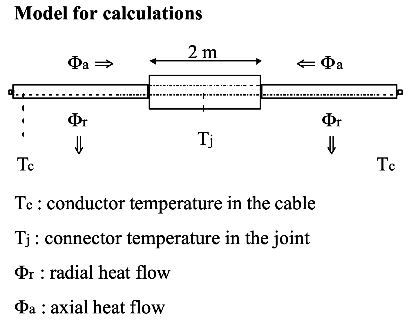
Joints and cables have different thermal properties. The basic differences can be expressed in thermal resistances and thermal time constants.
To verify the differences in the joint and cable temperature during one heating cycle, dynamical calculations were made for an 800mm2 132kV XLPE cable. First, the heating current is calculated to obtain a stable cable conductor temperature of 95 °C. Based on the heating current, the temperature was calculated inside the joint and cable for a period of 10h after switching on the current. The results are given in Figure 3 at a conductor heating current of 1800A.
| Model for calculations, © Cigré | Heating curve, © Cigré |
|---|---|
 |
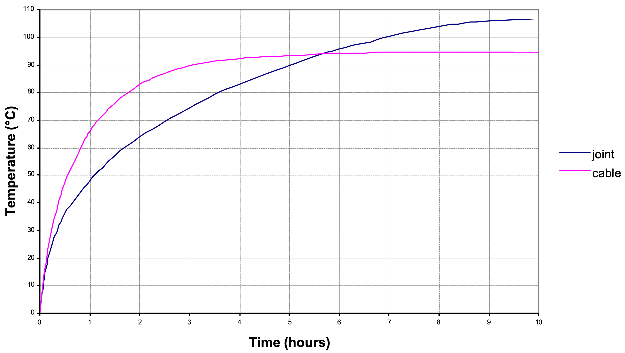 |
In stationary conditions, the joint reached a higher temperature than the cable, as a result of higher thermal resistance of the joint. In the first 6 hours of the heating cycle, the temperature in the joint is lower than in the cable due to the longer thermal time constant of the joint.