With the new version from September 2022, we introduce cable rating of buried cables using the Finite Element Method (FEM).
Posted 2022-09-03
Categories:
New feature
, Plots
, Theory
, Validation
The extensive python FEM module PyGimli is used for all our applications using the finite element method. Thanks to the contributors of PyGimli. In March 2022, we introduced calculation of the temperature distribution using FEM (see blog post). The FEM method removes some existing limitations in our project editor: Multilayer backfills can be used alongside regular backfills and empty backfills can be added.
The method is a hybrid between IEC and FEM. In a first step, the thermal resistances are calculated for each object considering all other objects, cables and backfills. In a second step, the standard IEC method is used to analytically calculate the rating and temperatures for all systems, including mutual heating. Thanks to using this combination of FEM and analytic method, the calculation is still very fast. In general, creating the mesh is what takes the longest. Solving the model is done quickly and so is the analytic calculation afterwards.
Let's look at an example where a thermal barrier is used to improve the thermal rating of a cable system by reducing the heat influx from a parallel district heating pipe (forward pipe at 90°C and backward pipe at 60°C).
The cable in the model is a theoretical construction with a diameter of 100 mm consisting of a 1000mm2 Al with DC resistance of 0.0291 Ohm/km and a diameter of 50 mm, covered by 20 mm of XLPE insulation with 3.5 K.m/W, no screen or sheath, plus 5 mm PVC jacket with 5.0 K.m/W. The cable has a T1 of 0.3274 K.m/W and T3 of 0.0838 K.m/W.
The ambient temperature is 20°C, the thermal resistivity of the soil is 1 K.m/W and of the 0.7 x 0.4 m backfill it is 0.4 K.m/W. The cable system runs at 800 A and for simplification at 1 kV, 0 Hz.
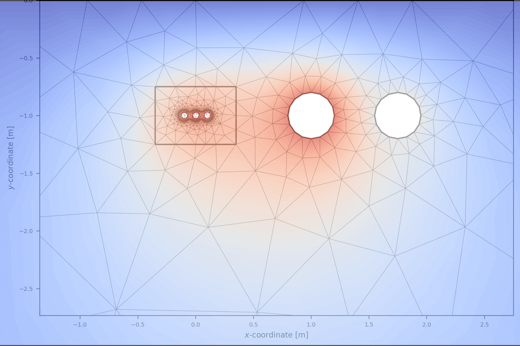
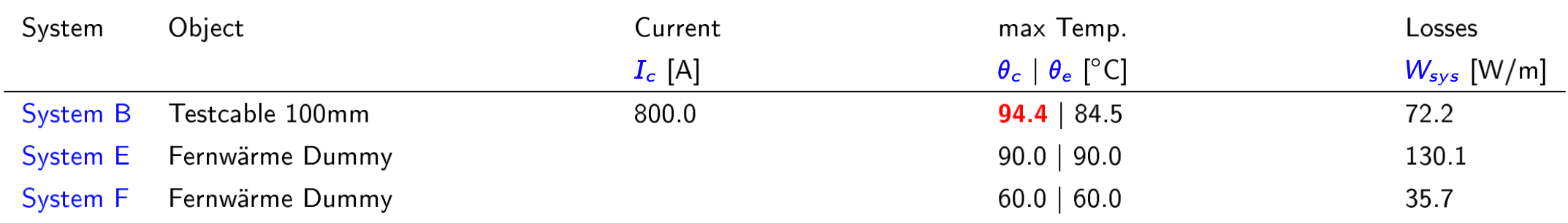
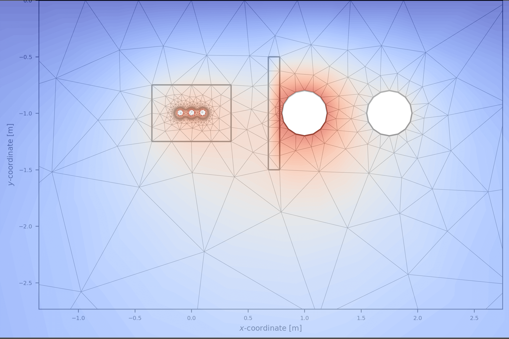
Due to the parallel district heating pipe, the cable system is overheated as the conductor tempeature reaches 95°C.
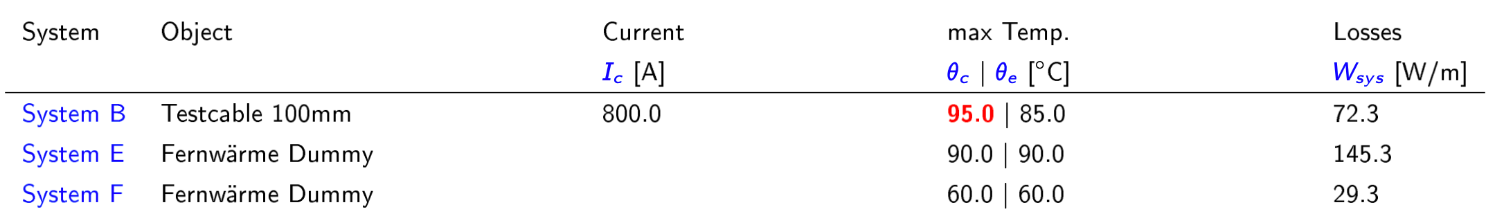
The heat from the district pipe is heating up the right side of the backfill area.
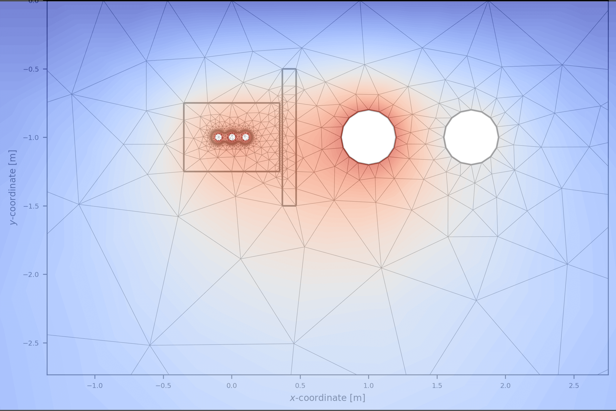
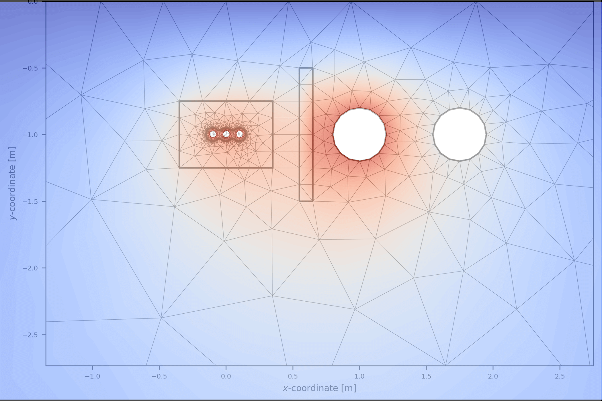
We have the idea to block the heat by introducing a barrier consisting of a 100 x 10 cm insulation material with a thermal resistivity of 25 K.m/W. Unfortunately, we now get an even higher temperature of the cable conductor of 96.6°C.
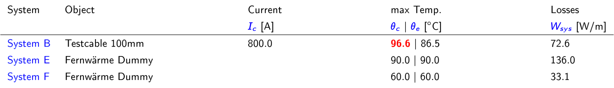
What happened? The heat generated by the cables can no longer flow away to the right side which has a negative effect on the cable rating.
| 1) No barrier | 2) Barrier next to the backfill |
|---|---|
 |
 |
Now we move the barrier away from the backfill and place it next to the district heating pipe and we get the desired effect, the cable system is now at 87.9°C and the losses are 1.6 W/m lower.
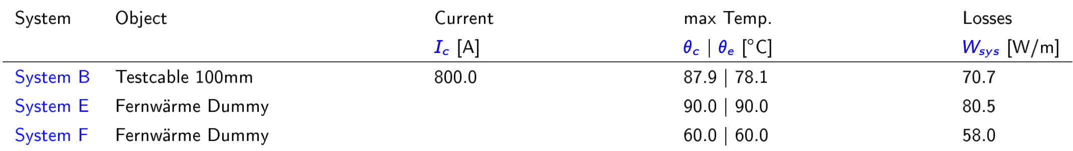
The heat contour clearly shows the effect of this barrier. Positiv side-effect: The barrier will reduce the heat losses from the heating pipe.
Last, we place the barrier in between backfill and heating pipe. As expected, the rating now is between case 2 and 3. The heat contour brings no surprises.
| 3) Barrier next to the heating pipe | 4) Barrier in the middle |
|---|---|
 |
 |
You have seen an example for an application of our new finite element method, an application which would have been impossible using the IEC method alone. Even more so, intuitively, we might have made situation worse by applying the thermal barrier at the wrong position.
We are very proud of our new method and wish you happy simulating.