With the multi-layer backfill method, it is possible to simulate the filling of a rectangular trench where the cables are buried with two superimposed horizontal layers of different materials, stacked above the cable bedding, respectively duct bank. Learn more about the method used, its range of validity, and its validation.
Posted 2021-05-19
Categories:
New feature
, Theory
, User guides
, Validation
Cableizer proudly announces the release of the multi-layer backfill method as a part of our buried module, according to de Lieto Vollaro et.al (see references below) including the following improvements:
According to de Lieto Vollaro et.al (see references below), the thermal resistance of a multi-layer backfill $R_{CG}$ is calculated by dividing the heat flow into three different paths as shown below in red.
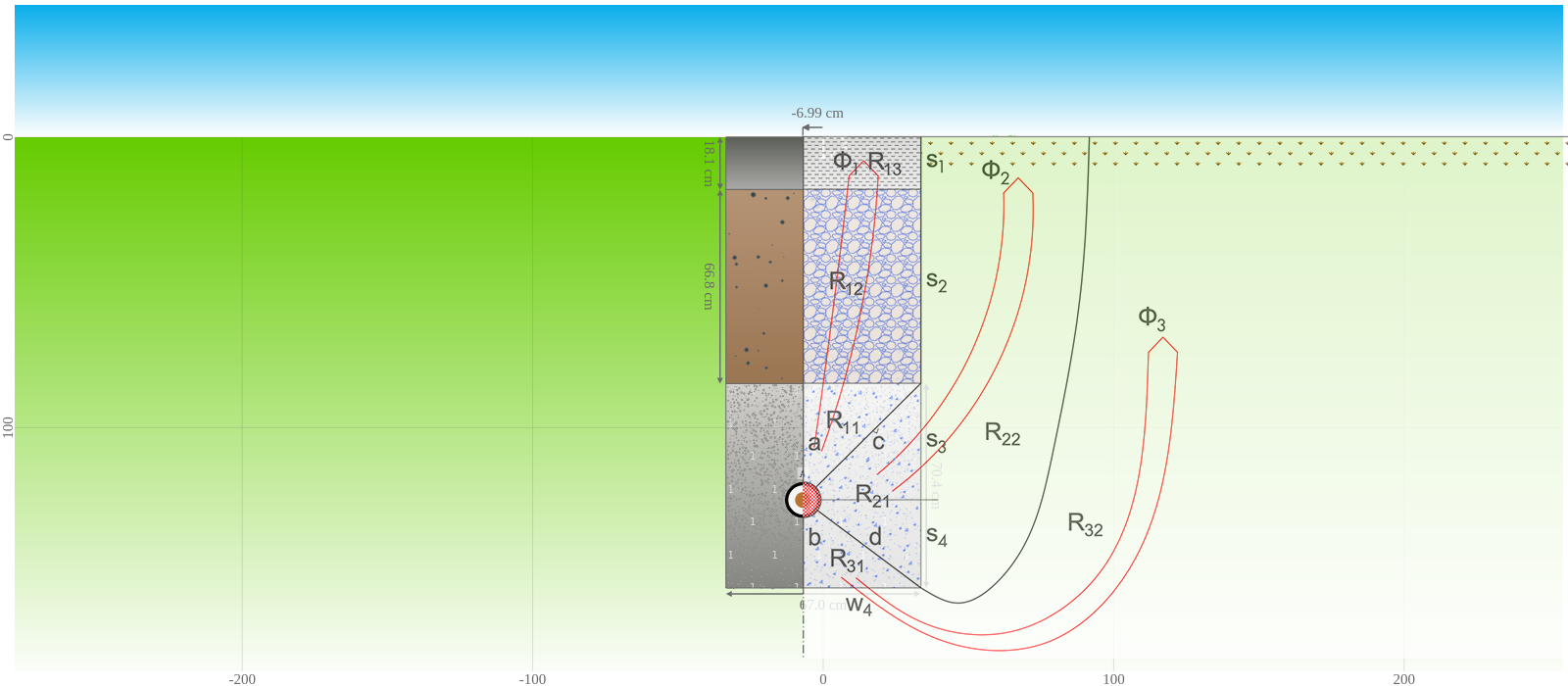
The thermal resistances for the three different paths are then calculated for both the left side and the right side (they are identical if the source is located in the center of the backfill), and the resulting thermal resistance is calculated by taking those values in parallel.
This method is based on fitting the thermal resistances to numerical data from finite element simulations. De Lieto Vollaro et.al defined equations for thermal resistances of different elements in the heat paths. The equations use the constants $C_1$ to $C_7$ which were defined in the papers. As a consequence, the method is limited to the conditions described in the following section.
Cableizer verifies that the multi-layer backfill arrangement is within the following limits of parameter variability. If the values are outside this range, Cableizer displays a warning. However, it is still possible to run simulations, but result may be implausible.
| Parameter | Symbol | Range |
|---|---|---|
| Thickness of surface layer | $s_{b1}$ | 0.048 - 0.16 m |
| Thickness of middle layer | $s_{b2}$ | 0.2 - 1.5 m |
| Thickness from object to top of bedding layer | $s_{b3}$ | 0.3 - 1.3 m |
| Width of the backfill | $w_b$ | 0.41 - 1.4 m |
| Trench depth of multi-layer backfill | $L_{b4}$ | 1.02 - 2.55 m |
| Depth of laying | $L_{cm}$ | 0.66 - 2.24 m |
| Thickness from object to bottom of bedding layer | $s_{b4}$ | 0.17 - 0.48 m |
| Ratio of width of the backfill to the trench depth | $w_b$/$L_{b4}$ | 0.215 - 1.264 |
| Thermal resistivity of surface layer | $ρ_{b1}$ | 0.52 - 9.80 K.m/W |
| Thermal resistivity of middle layer | $ρ_{b2}$ | 0.52 - 9.52 K.m/W |
| Thermal resistivity of backfill | $ρ_{b}$ | 0.52 - 7.14 K.m/W |
| Thermal resistivity of soil | $ρ_{4}$ | 0.31 - 8.62 K.m/W |
These many conditions seem to be somewhat restrictive, but the range is often well-sized and should cover most applications.
For validation, the ampacity for one single-core cable with a limiting temperature of 90 °C was calculated according to the arrangement in the figure above. Validation is based on simulating directly buried (Case A), standard backfill according to IEC 60287-2-1 Ed. 1.2 (Case B), and multi-layer backfill (Case C) for the same conditions.
| Case | Calculation method | $\rho_4$ | $\rho_b$ | $\rho_{b1}$ | $\rho_{b2}$ | $I_c$ |
|---|---|---|---|---|---|---|
| 1A | Directly buried | 1.0 K.m/W | - | - | - | 894.6 A |
| 1B | Standard backfill | 1.0 K.m/W | 1.0 K.m/W | - | - | 894.6 A |
| 1C | Multi-layer backfill | 1.0 K.m/W | 1.0 K.m/W | 1.0 K.m/W | 1.0 K.m/W | 893.5 A |
| 2B | Standard backfill | 1.0 K.m/W | 0.7 K.m/W | - | - | 965.8 A |
| 2C | Multi-layer backfill | 1.0 K.m/W | 0.7 K.m/W | 1.0 K.m/W | 1.0 K.m/W | 963.8 A |
| 3C | Multi-layer backfill | 1.0 K.m/W | 0.7 K.m/W | 1.5 K.m/W | 1.5 K.m/W | 946.0 A |
| 4C | Multi-layer backfill | 1.0 K.m/W | 0.7 K.m/W | 2.5 K.m/W | 1.5 K.m/W | 941.6 A |
For Case 1 the thermal resistivity of soil and all three backfill layers is the same and equal to 1.0 K.m/W, which should result in the same ampacity independent of the calculation method. This is almost correct with a difference of only 0.1 % for the multi-layer backfill method as compared to the other two methods (which inherently have the same result).
For Case 2 the thermal resistivity of the backfill has been reduced to 0.7 K.m/W, while all surrounding soil has an unchanged thermal resistivity. In this case the difference between the two methods is 0.2 % which is a very good agreement with consideration to the nature of the multi-layer backfill method. The ampacity is as expected increased due to the decrease in thermal resistivity of the backfill.
When the top and middle layers are filled with higher thermal resistivity material of 1.5 K.m/W (Case 3C), the ampacity is as expected decreasing compared to case 2C. The ampacity does further decrease when the top layer is modelled as a street with a even higher thermal resistivity of 2.5 K.m/W (Case 4C). These numbers look all reasonable in relation to each other. Unfortunately, the two reference publications do not include similar case studies for comparison.
R. de Lieto Vollaro, L. Fontana, A. Vallati, 'Thermal analysis of underground electrical power cables buried in non-homogeneous soils', Applied Thermal Engineering 31, 2011, p. 772-778
R. de Lieto Vollaro, L. Fontana, A. Vallati, 'Experimental study of thermal field deriving from an underground electrical power cable buried in non-homogeneous soils', Applied Thermal Engineering 62, 2014, p. 390-397
/static/